Pololu Blog »
Paul's dead reckoning robot
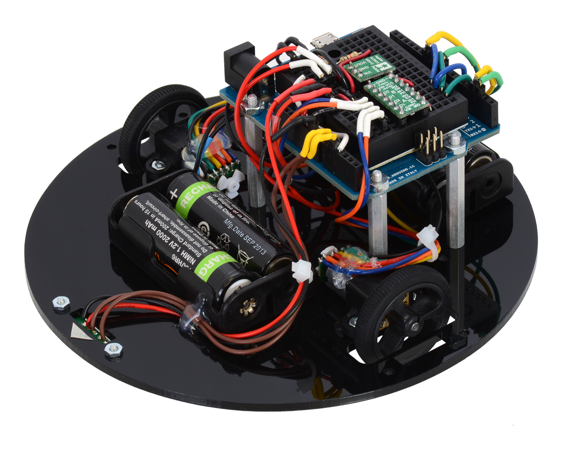 |
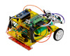
This post is about my first-place entry in the 2014 LVBots Dead Reckoning Competition, a 150 mm round robot named paul-dead-reckoning2.88ec5df. I designed this robot around the Arduino Leonardo, with the intent that it would be usable for both dead reckoning and line maze competitions. It is mechanically similar to the 3pi, but larger, to leave room for custom parts such as the quadrature encoders that make dead reckoning possible.
Motivation
Since I wanted this robot to be larger and more powerful than the 3pi, I decided to use four NiMH AA batteries (4.8 V) as a power source. At this voltage, the 30:1 Micro Metal Gearmotors HP with Extended Motor Shafts and DRV8835 Dual Motor Driver Carrier are a nice combination that makes the robot theoretically slightly faster than the 3pi.
The regulator on most Arduino boards requires over 7 V to work properly; I decided to bypass that and get 5 V from a S7V7F5 Step-Up/Step-Down Voltage Regulator. The regulator can supply about 1 A, more than enough to power everything, with plenty of capacity for future additions.
Note: I connected the 5 V output of my regulator directly to the 5 V line of the Arduino, which effectively shorts it to the USB bus voltage if you turn on the power switch while it is plugged into a computer. I was lucky and did not experience any problems, but this is generally not a good idea!
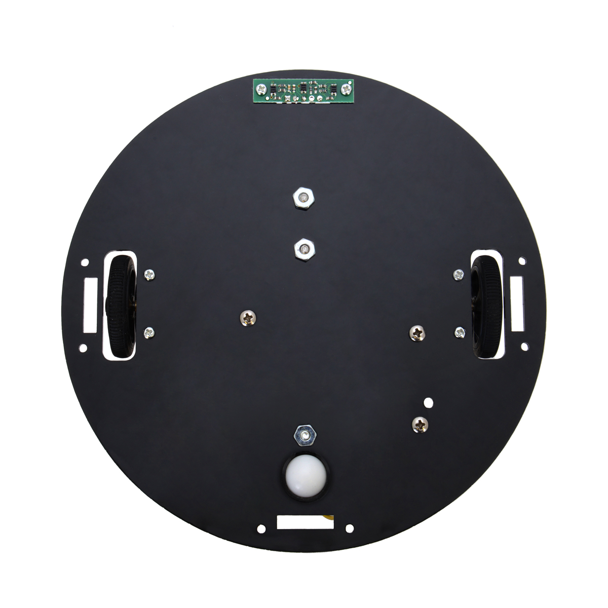
For line following, Pololu carries two different kinds of reflectance sensors: analog sensors, which use a pull-up resistor to produce an analog voltage related to the amount of reflected light, and RC sensors, which rely on precise timing of a transition on a digital input for an “analog” measurement. The RC sensors have generally been better for the kinds of robots we build, which is why we put them on the 3pi, but there is a potential problem when using them with quadrature encoders: counting encoder ticks requires high-priority interrupts, introducing random delays into the RC timing procedure. To avoid random inaccurate readings, I selected the analog QTR-3A Reflectance Sensor Array.
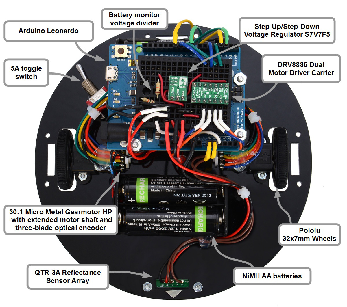 |
Top view of paul-dead-reckoning2.88ec5df. |
|---|
Complete parts list
Mechanical parts:
- A custom chassis laser-cut from 1/8" acrylic; design available in the GitHub archive.
- Pololu 32×7mm wheels
- 2 × 30:1 Micro Metal Gearmotor HP with Extended Motor Shaft
- 3pi ball caster
- Pololu micro metal gearmotor brackets
- Aluminum standoffs, various screws and nuts, cable ties, double-sided foam tape, and hot glue.
Power:
Sensing:
Electronics:
- Arduino Leonardo
- A 170-point breadboard
- Pololu 5V Step-Up/Step-Down Voltage Regulator S7V7F5
- DRV8835 Dual Motor Driver Carrier
- A voltage divider for battery voltage sensing.
- Various wires, headers, and heat-shrink tubing.
Arduino pin selection
I used Arduino pins 9 and 10 as my motor PWM lines so that I could adapt the Timer 1 code from the ZumoMotors Arduino Library to drive them. For accurate encoder counting, I needed hardware pin-change interrupts. To achieve this, I put one encoder on pins 2 and 3, which I configured to trigger interrupts INT1 and INT0, respectively, and I put the other on pins 8 and 11, which I configured to trigger PCINT0. This way, I was able to use separate interrupt routines for the two encoders, making the interrupts simpler and faster.
I used only the outer two sensors on the QTR-3A, which I connected to Arduino analog inputs 0 and 1, and I connected a resistor voltage divider on the battery voltage to analog input 2 for battery voltage monitoring.
Out of the remaining pins, 4 and 5 seemed relatively uninteresting, so I used them as motor direction control lines.
Code
The code I used for the contest is available in commit 88ec5df of my GitHub repository, which is where my robot gets the last part of its name. The core is an update routine that uses simple integer arithmetic, approximating trigonometric calculations, to compute the robot’s position heading. Here it is, in a slightly simplified and less accurate form:
  int16_t dc = + n*s/STEPS_PER_RADIAN;
  int16_t ds = - n*c/STEPS_PER_RADIAN;

  c += dc;
  s += ds;
  x += n * c;
  y += n * s;
The snippet above represents the update that is run on each forward (n=1) or backward (n=-1) encoder tick from the left wheel. The 16-bit integer variables c and s represent the cosine and sine of the heading, and the 32-bit integer variables x and y are its coordinates on the playing field. You can see the complete update code, which includes leap ticks and a better trigonometric approximation, in the functions ticks1() and ticks2().
The rest of the code handles finding and following the line, then following an imaginary line back to the starting point. There are many ways to follow an imaginary line, but I did it by programming the robot to always follow the negative x-axis in its coordinate system back to the origin. Basically, when the robot is far from the x-axis, it tries to turn toward an angle of approximately 45 degrees, and as it gets closer to intercepting the axis, it progressively reduces that angle. You can see how I implemented that in the function goHome().
To use goHome() when starting at an arbitrary point, the robot first performs a coordinate transformation that puts the robot onto the negative x-axis. That transformation is the most mathematically interesting part of the code, so here it is, again slightly simplified (see complete code here):
void transform() {
  double r = hypot(x, y);
  double nx = (double)x/r;
  double ny = (double)y/r;
  int16_t new_c = -nx*c-ny*s;
  int16_t new_s = ny*c-nx*s;
  c = new_c;
  s = new_s;
  y = 0;
  x = -r;
}
As you can see, I used floating point variables in this function. Floating point calculations can be extremely slow on 8-bit microcontrollers, so you should generally avoid them, but since I only had to run the function once, I decided that it was not worth optimizing.
|
|
Testing and calibration
I discovered early on that the robot lost accuracy at high speeds, probably due to skidding, and since the contest scoring algorithm makes speed almost irrelevant, I limited the motors to about 25% of full power. At this slow speed, on any given course, it tended to be precise (always ending up at the same spot) but not accurate (the spot was far away from the target). Through trial and error, I adjusted two calibration parameters to get the best possible accuracy.
The first calibration parameter represents the turning angle resulting from a single encoder tick on one of the wheels. I started with a rough guess at the value, then had the robot drive through some simple circles to refine it, ending up with a final value of about 410 ticks per radian.
The second calibration parameter is needed because the two wheels behave slightly differently (e.g. maybe they have slightly different diameters); without accounting for this my robot systematically drifted to the right of its desired path. Since I was using integer variables everywhere, I couldn’t just use, say, 410 ticks/radian for the right wheel and 412.563 ticks/radian for the left wheel. Instead, I inserted an extra “leap tick” after recording a certain number of ticks – it turned out that adding a leap tick for every 160 normal ticks corrected the drift.
Results
On various trials, paul-dead-reckoning2.88ec5df was able to consistently return to within about 6 inches of its initial position. My first attempt running on the final competition course resulted in a disqualification, because I positioned the robot behind the starting point, which was marked with black electrical tape, confusing the sensors. We replaced the electrical tape with a small ink dot, and its second run went smoothly, resulting in a final error of about two inches and winning the competition!
For contest video and links to posts about the other robots, see our main blog post about the dead reckoning competition.
Related products


-
Claire's dead reckoning robot
- 28 March 2014Like several of the other engineers here at Pololu, I made a robot to compete in the LVBots Dead Reckoning Competition that took place recently....
-

New product: 130-size, high-power brushed DC motor
- 3 April 2014These new 130-size motors are great for applications that require a lot of power in a small package. They are a generic alternative the Solarbotics...
3 comments


Post a comment


Home | Forum | Blog | Support | Ordering Information | Lists | Distributors | BIG Order Form | About | Contact
© 2001–2026 Pololu Corporation
