Pololu Blog » Engage Your Brain »
Advanced hobby servo control using only a timer and interrupts
In this last article about generating pulses for hobby servo control, I will present what I think is the best solution to controlling many servos or controlling some servos while still leaving enough processing time to do other tasks. It’s not that easy to make this approach work well, so my recommendation in most cases is just to get one of our servo controllers, which use this technique.
As I have been repeating for the last several posts (starting around here), the target signals we are generating are square waves with a frequency of approximately 50 Hz, with the only crucial parameter being the positive pulse width. This means that if we want to control 20 servos, we only need to generate a total of 1000 pulses per second. Even if we spend 20 us on each rising and falling edge, we would still have 60% of our processor time available for doing other things. The only difficulty is that we must not get ourselves into a situation where we must tend to more than one pulse at the same time; otherwise, at least one of the pulses will end up with the wrong length and cause the corresponding servo to jump around.
As a reminder, generating up to 8 channels at up to about 50 Hz does not require simultaneous pulse generation, so all this makes sense only if you need the extra channels or higher pulse frequency. The basic principles apply to any number of channels; I will use four in my diagrams, which should be enough to get the points across. Although it’s easy to start all the pulses at the same time, it should be obvious that that can’t work since multiple channels might be set to the same pulse width:
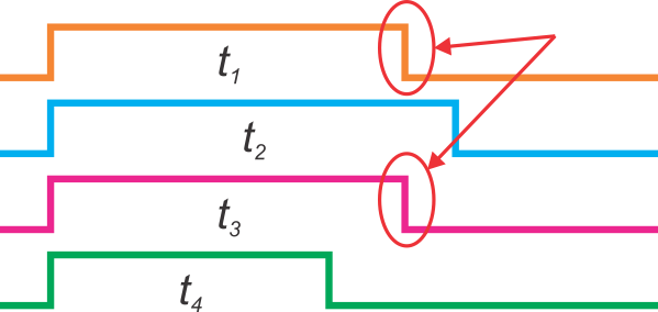 |
It need not even be the exact same pulse width that causes the problem since any pair of pulses closer than the time we need to switch from ending one pulse to ending another pulse is problematic. It is also not enough simply to stagger the beginnings of the pulses since the offsets might exactly match the differences in pulse widths of some pair of channels and again require us to service multiple pulses at the same time:
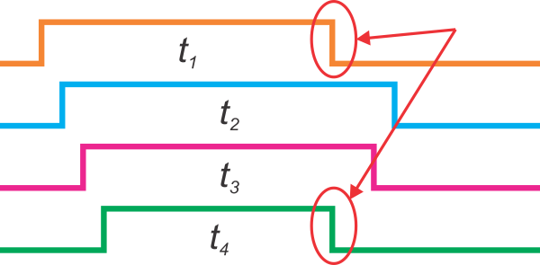 |
It should be clear now that we have to somehow take into consideration all of the pulse widths before we begin any of them: we have to schedule all starting and ending pulses in a way that assures us no two edges happen within some minimum time of each other. I was pretty excited about it when I figured out my fairly simple solution to this scheduling problem. I think it’s a good exercise, so I’ll change topics a bit before revealing my solution. If you think of any other way to do the scheduling, please share it in the comments.
This scheduling stuff is kind of a high-level consideration, at least as far as this application goes. However, regardless of how we implement that high-level scheduling, the low-level details are very important, too. My assumption so far has been that we can somehow make the correct edge on the correct channel at the correct time. The minimal way to do that is to have a timer and associated interrupt, which I described briefly in my previous post. Because the timing for these servo pulses is so critical, and because we are counting on no other hardware to do our I/O pin manipulation, this timer interrupt must be of the highest priority. (In our original servo controller, the timer interrupt was the only interrupt, and everything else was handled without interrupts. On our newer Maestro servo controllers, the microcontroller has two interrupt priorities, and the timer interrupt is the only high-priority interrupt.) Taking over the highest-priority interrupt puts limitations on the rest of the application running on the microcontroller, so it is essential for the interrupt routine to be very quick.
In addition to commandeering the timer and highest-priority interrupt, we still have to figure out a way to represent what we want to do (start a pulse or end a pulse), which channel or I/O pin to do it on, and how to rearm the timer interrupt to happen again in the right amount of time. The part of the interrupt routine that reads the data structure and modifies the I/O pin and timer must be written to take the exact same amount of time regardless of what event is happening, or the various execution paths through the interrupt routine must be timed and compensated for. For instance, doing some kind of generic pre-computed bit manipulation might look like this:
port &= portANDmask;
port |= portORmask;
where portANDmask and portORmask are pre-calculated to cause the right pin to be cleared or set. However, even in this minimal example, the timing is different if the pin is being cleared or being set. I think this is enough to illustrate a bit of the flavor of what is involved in getting the interrupt routine right. The complexity is ultimately dependent on factors like the features of your MCU, what kind of performance you need, and what kind of tradeoffs you have available. As an extreme example, you could implement a 20-servo controller with a 40-way switch or calculated jump:
// do some things common to all possible pins/events
switch ( thingToDo )
{
	case 0:		// turn on channel 0
			break;
	case 1:		// turn on channel 1
			break;
	case 2:		// turn on channel 2
			break;

	...

	case 20:	// turn off channel 0
			break;
	case 21:	// turn off channel 1
			break;
	case 22:	// turn off channel 2
			break;

	...
}
// wrap up interrupt routine
You might need to do some programming in assembly language or at least check your compiler output to verify the uniformity of all of the times from the start of the interrupt routine to the execution of the desired pin change.
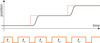
Now, back to the scheduling question: did you come up with an algorithm? I’ll show you the diagram first as a final hint before describing it:
 |
The trick is to sort the pulses from shortest to longest and then generate the pulses in that order with staggered starts. Since every pulse can be no shorter than the one that precedes it, the timing between pulse endings will be at least as long as the amount by which we stagger the offsets. As long as that offset amount is longer than our worst-case interrupt routine time, we are all set. It might help to visually rearrange the pulses to be in the order they are generated:
 |
Part of the fun of this solution is that you can put into practice those sorting algorithms that you learned in your introductory programming class! Since we have a small set of numbers to sort, we do care about the implementation details as much as about the order of growth of your algorithm. On the old servo controller, which does 16 servos, we broke them up into four groups of four, so we only had to sort four numbers; we just did a bubble sort for that. The newer Maestros sort all 24 channels; we clocked various algorithms in simulation and settled on a merge sort written in assembly.
Conclusion (for now)
I think I am done writing about how to generate servo control pulses. Ultimately, if you only want to do a few servos, it’s pretty easy; if you want to do many, it can get quite difficult, so you might be better off getting a dedicated servo controller. Next time, I plan on writing about the somewhat-related topic of speed and acceleration control of servos.
-
Learning PID values using simulated annealing
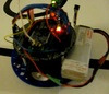
- 29 April 2011This is a video of a robot based on the Pololu 5" robot chassis that automatically improves its PID constants over time.
-
RC servo speed control
- 6 May 2011It is often desirable to control the speed and acceleration of hobby RC servos. Understanding your options can be confusing since there are various...
7 comments

if i staggered the start of the pulses then for example if the t4 pulse is the longest in the second "block" of pulses the time between the two pulse is not 20 ms but more.
Thank fo the help
Augusto

- Jan

Just one thought that you probably already implemented in your product. Since you have sorted all your pulse and know the minimal required time, u can release that time period to do other things. So here is how i implement it. 1) sort the pulse time. 2) write that minimum pulse (minus) some of that to variable. 3) put that variable into a Timer for overflow interrupt....
I'm not sure what your point is or that you understand the extent to which the interrupts are used. All pulse activity, both starting and ending, is done in the interrupt routine, so all the other time is already available for other things.
- Jan
Apologies for my bad English. Guess I was listening too much Japanese Songs XD. Yes, all the servo control pulses are done in an interrupt loop. So consider that a typical servo control pulse is in range from 0.5ms to 2.5ms. So the longest interrupt loop for controlling those servos is about 2.5ms. But u can reduce the idle time by at least 0.5ms becuase the only thing the MCU doing is set some pins high at the stating 0.5ms period. Therefore, what i did in my code is:
a) Start a new 20ms period, do the sorting and set all the needed pins.
b) put the minimal value into a Timer Counter waiting for the overflow and leave the interrupt.
c) Once the minimal pulse reach to its end, come back to the interrupt and start to reset everybody
Hope that helps. And thx again for your tutorial!
Looks like you still do not quite understand the interrupt scheduling. There is no "interrupt loop" or anything special about the beginning of the pulse generation or the first 0.5 ms or the first 2.5 ms. Once the events are scheduled, each pulse starting or ending triggers a separate entry into the interrupt routine, which just does a single bit setting or clearing before setting up the next interrupt end getting back out of the interrupt routine.
- Jan
-Katlv
Post a comment


Home | Forum | Blog | Support | Ordering Information | Lists | Distributors | BIG Order Form | About | Contact
© 2001–2026 Pololu Corporation


