Pololu Blog » Engage Your Brain »
RC servo speed control
It is often desirable to control the speed and acceleration of hobby RC servos. Understanding your options can be confusing since there are various speeds involved, many similar terms are used, and the terms are not used consistently by different companies or end users. You might also have an idea of what you want your servo to do without knowing what to call it or how to describe it or how to implement it. To get a good understanding of what is going on, it is helpful to picture the position of your servo in relation to the commands you are sending it. A simple first attempt might look like this:
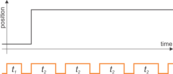 |
I have deliberately shortened the space between control pulses so that we can see several pulses at once. The problem with this representation is that it suggests that our servo can instantly move from one position to another. We know that our servos are not infinitely fast, so we can improve the drawing by explicitly showing that it takes our servo some time to move from one position to another. I hope you noticed that the diagram also suggests that our servo can see into the future, moving to the new position before the pulse commanding it there even finished. So, here is a better approximation:
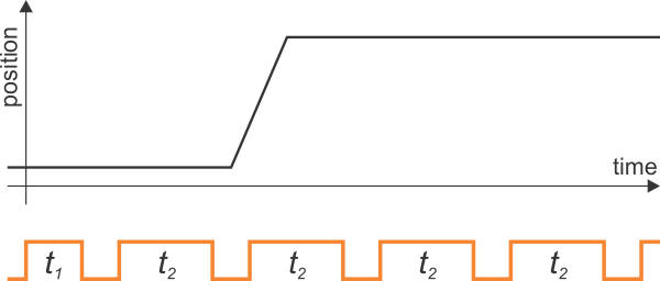 |
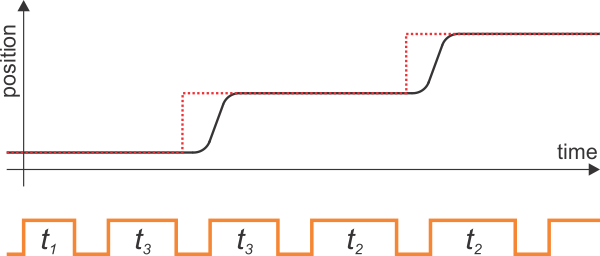
The diagram now makes explicit that the servo cannot begin moving until after we have given it a new position command and that it takes some time to move from one position to another. However, since I also want to include some discussion of acceleration, the diagram is still too simplistic in that it suggests that our servo can instantly get up to full speed. In reality, it takes time to accelerate to that speed, and the servo needs to slow down (decelerate, or accelerate in the negative direction) before it gets to the new position, so the picture you should have is more like this:
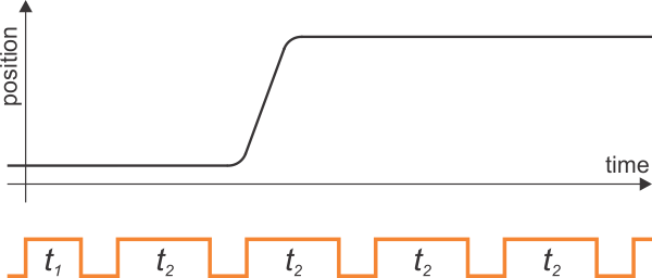 |
Everything so far has just been about the intrinsic properties of a servo: when you tell it to go from one position to another, it’s going to do that at the fastest speed it can, and there is nothing you can do to increase that. Therefore, any discussion about servo speed control can only be about making a servo move more slowly than it would on its own. At this point, we should add to our mental model the idea of a servo’s target position. I have added it to the diagram as a dotted red line:
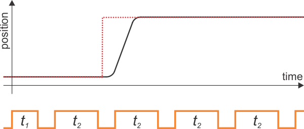 |
This red target line represents the servo’s understanding of what we told it to do via the command pulses: as soon as the first pulse of length t2 arrives, the target is changed, and the servo begins its task of actually making the position match the target. As I hope I have belabored by now, we do not get any feedback from a servo: we do not know what its target is or what its output position is or how hard the servo is trying to achieve what we are telling it to do. All we get to do is to manipulate the target line, and trust that the servo will get us there.
So, to make a servo move slowly, we have to tell it to move slowly, and the way to do that is to move the target slowly. The crudest implementation would be to insert some intermediate position commands, like this:
 |
The diagram represents what might happen if you use a dedicated servo controller but do not use its speed control feature (sometimes called “ramping”): if you send intermediate position commands at a speed slower than the servo can achieve them, the servo will at times be moving at full speed and at other times be stopped when it has caught up to the target. Therefore, the trick to smooth, low-speed movement is to change every single pulse you send the servo. This is why you have to implement speed control yourself if you are directly generating the speed control pulses or use a servo controller that has speed control support; having to send a dedicated servo controller 50 commands per second, even if you could synchronize them just right, would defeat the purpose of a dedicated servo controller. If your servo controller has a speed control feature, you can set the speed at which you want the servo to move, and when you send a new position command, it automatically calculates and sends all the intermediate pulses.
Let’s consider a specific example: we want to have a servo sweep a 90-degree range in five seconds. This corresponds to approximately a 1 ms (the exact amount will depend on the servo) cumulative change in the pulse width over that period. In five seconds, we will send 250 pulses, so we need each pulse to be 4 microseconds longer than the previous one. Again, keep in mind that although the servo itself is using closed-loop feedback, we are out of that loop. If an external force keeps the servo from moving, we can’t know that (without extra sensors or electronics), so we keep gradually moving the target. Once the servo is freed, it will move to the current target position as quickly as it can:
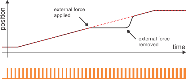 |
This situation is similar to the problem that arises on power-up: if we do not know where the servo is to begin with, we cannot make the first movement slow: we have to send the servo some kind of target position, and it will exert all the power it can to get to that as quickly as possible.
I should point out that the terms “position” and “target” that I have been using could mean different things depending on your perspective. If you have a main robot controller, it might have its own variable that is called either the position or target, which can then get sent to a servo controller via a “set position” command that then sets the servo controller’s idea of a target, which might be used to send the servo yet another sense of target. It should be clear from the context of what you are working with, but make sure to pay attention to it. In the diagram below, I have added the dashed green line to represent a “position” that might have been sent to a servo controller that has speed control. Keep in mind that even if the servo controller gives you a “get position” command, it can only return the red or green value, not the actual position of the servo.
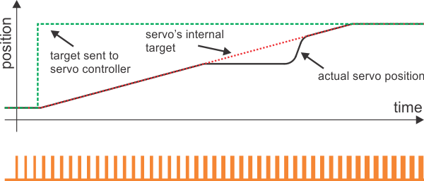 |
The basic principles are the same for acceleration control and any other more advanced motion control and trajectory planning: we are free to calculate whatever target position curve we want to and then to send the corresponding pulses; as long as the servo is capable of executing that path, it will, and if is not capable of it, we will not know about it. This can get arbitrarily difficult, but in the case of acceleration, you don’t need more than basic algebra (you need more math to really understand the physics of acceleration than to implement the corresponding servo control on a microcontroller). Acceleration control tends to make sense only on longer movements where you want to get up to a fairly good speed but want to get there gradually, so if you do not have a trivial way of achieving it (e.g. with a servo controller that just gives you that feature), it might not be worth it unless you specifically need to speed up your long movements without a lot of jerking around at the beginning and end of the movement.
Conclusion (for now)
I hope I have presented enough information to show how to implement speed control with hobby servos and to generally show that once you understand the basic interface, you can make a servo do anything a person can make it do with a joystick and that at that point, the problem moves on from being specific to RC servos to a problem of mathematically representing the movements you want to achieve. Next time, I plan on moving back to more electromechanical considerations about servos. Looking at my notes, I see there are still so many frequently asked questions to cover!
-
Advanced hobby servo control using only a timer and interrupts
- 5 May 2011In this last article about generating pulses for hobby servo control, I will present what I think is the best solution to controlling many servos or...
-
Instructable: Introducing the Wixel USB Wireless Module
- 6 May 2011This Instructable by customer Michael Oz introduces the reader to the Wixel through a series of basic projects.
6 comments


The Maestros should give very good, smooth outputs, so the jerkiness is probably because of the servo you're using or the load you have on it. You're probably effectively getting a situation like the one in the last two diagrams, where the commanded position is gradually changing but the servo responds in jerks either because it isn't very good or because you have so much load on it that it can't move until the error is quite big. Can you put the same servo setup on an RC receiver and slowly move the controls on your transmitter?
- Jan

- Jan

I am working on a project using an arduino to control a servo motor using the error. How can I implement impulse with modulation in my code to make the servo motor speed up when the error is large and slow down when the error is small?
-Paco
The hobby servos I wrote about in this article are not well suited for doing what you are asking for since they do not tell you the error. You can do something similar to the speed control I wrote about by picking a virtual set point and then sending your servo appropriate commands based on where you think the servo should be, having it move faster when farther from the point and slower when near that set point. However, this is all just an open-loop motion sequence you would be sending the servo, and depending on the resistance it encounters, the actual resulting movement can be completely different from what you intend.
If you are looking to effectively make your own servo by doing your own closed-loop control system, that is outside the scope of this article, and you should search online for things like "closed-loop motor control with Arduino" as there are many resources available.
- Jan
Post a comment


Home | Forum | Blog | Support | Ordering Information | Lists | Distributors | BIG Order Form | About | Contact
© 2001–2026 Pololu Corporation


