Pololu Blog » Engage Your Brain »
Simple microcontroller approach to controlling a servo
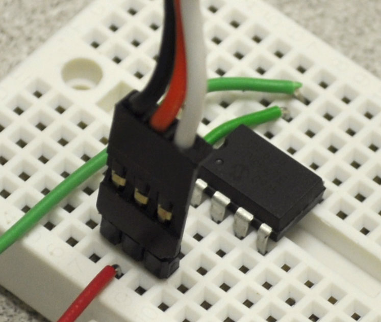 |
One-component servo controller circuit. |
|---|
Today, I want to discuss the microcontroller equivalent of the simple servo control circuit I presented last time. As I mentioned then, the circuit is about as simple as it can be, yet it requires eight components to arrive at a sub-optimal servo control waveform. Some of its deficiencies, such as the slow rise time of the pulses, can be addressed by slightly more advanced circuits that might implement an astable multivibrator using an integrated circuit such as the famous 555 timer. In terms of part count, the 555-based servo controller might be a bit better than the two-transistor approach, but the 555 has many transistors inside it. As long as we are comfortable categorizing a component with many transistors inside it as a single part, we might as well skip the 555 and go straight to a low pin-count microcontroller, which has thousands of transistors inside it and which will allow us to make a far superior, single-component servo controller.
I will repeat my reminder that you can destroy a servo by commanding it past its mechanical limits, so any time you’re making your own servo control devices, be careful. You can limit the likelihood of destruction by operating your servos at a relatively low voltage, so they cannot develop as much torque as they are capable of. I also recommend testing any circuits with a standard servo, which is relatively cheap, more robust than smaller micro servos, yet not powerful enough to easily destroy itself. If you see or hear a servo straining against its end stop, or if it’s getting hot, you should disconnect it or turn off your power immediately.
Also as a review from previous posts, let’s go over the basic signal we’re trying to generate: a square wave with a variable positive pulse width of around 1 to 2 milliseconds and a frequency of around 50 Hz.
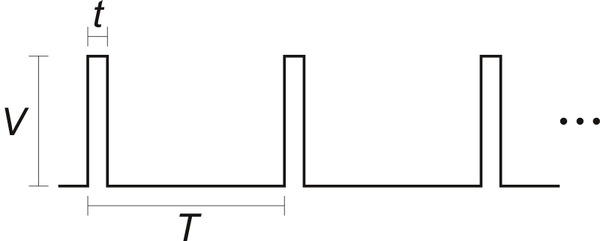 |
Our voltage, V, should be around 3 volts or higher; we need the pulse width, t, to be variable since that is what encodes the desired servo position; and as we saw in servo control interface in detail, the period, T, can affect how hard a servo tries to maintain a position and should be around 20 ms but otherwise is not that critical.
Many microcontrollers can run on 3 to 5 volts, so the V requirement can be satisfied with a normal digital I/O line: all we have to do is toggle that line with the appropriate timing. This makes for a very simple program:
loop:
	make pin high
	wait for time <t>
	make pin low
	wait for time <T-t>
	go to loop
Since we do not care much about the period, T, we can do the same simplification we did with the two-transistor circuit: make the low part of the pulse basically fixed. That way, we do not have to worry about how long we spent making the high part of the pulse:
loop:
	make pin high
	wait for time <t>
	make pin low
	wait for around 18 ms
	go to loop
My “programs” so far are more English than some specific programming language, but it should be easy to see how to do this in your favorite language. If you have the right libraries or basic commands, the first three lines can even be combined into a single command for making a pulse. For instance, the PBASIC version for the BASIC Stamp might look like this:
loop:
	PULSOUT 1, 750		'make a 750 * 2 = 1500 us pulse on pin 1
	PAUSE 18			'do nothing for 18 ms
	GOTO loop
The C equivalent might look more like this:
while ( 1 )
{
	pulse_out(SERVOPIN, 1500);	// assuming pulse_out() takes an argument in us
	delay_us(18000);
}
Note that in the PBASIC example, PULSOUT and PAUSE are built-in commands, whereas the pulse_out() and delay_us() functions in the C example are something you would need to also write yourself (or find in a library).
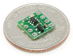 |
One of the benefits of implementing your servo control on a microcontroller is that you can put your code on a little 6-pin microcontroller or on a big, 100-pin part. In the case of the 6-pin microcontroller, you might not have much program memory, and it might make more sense to write simple servo control firmware in assembly. In the same sense that the two-transistor circuit is more a good exercise than a great engineering solution, the assembly-language servo controller is a good project to try some time.
The two specific examples above were for fixed pulse widths of 1.5 ms. Obviously, that does not make for a particularly interesting servo controller. The great thing about a microcontroller solution is that you have a lot of flexibility, and we can use the time between pulses to decide what to do next. For instance, instead of just pausing for 18 ms, we could read a potentiometer or some buttons or do some calculation about how we want the servo to move on its own (e.g. sweeping back and forth).
If you want to make more than just a single-channel servo controller, it can still be quite easy as long as you can structure the rest of your project’s functions around the servos’ requirements. For instance, you could control a simple robot with four servos using this general control loop:
loop:
	make the pulse for servo 1
	make the pulse for servo 2
	make the pulse for servo 3
	make the pulse for servo 4
	read sensors
	recalculate servo positions
	pause if necessary
	go to loop
In this scenario, we would spend four to eight milliseconds generating the four servo pulses (depending on how long the pulses need to be for each servo), which would leave us a little over 10 ms to read our sensors and decide what we want to do with the sensor data. The key is that the exact timing of the extra operations do not matter, but we can pause at the end of our loop to get a consistent 50 Hz update rate if we think that consistency is worth it. However, the time for making the individual pulses must be dedicated completely to the servo control operation; if we are even a few microseconds off in our pulse widths, the servos will start twitching.
Conclusion (for now)
This was a very simple introduction to what is involved in controlling a servo from a microcontroller. If you just need to control a few servos, and do not need to do much else, it is indeed quite simple. Next time, I will move on to more advanced considerations for controlling many servos at once or controlling servos without having to tie the rest of your program to the servos’ 50 Hz update cycle.
-

Build Yourself a Bluetooth Controlled Six-Legged Robot
- 4 March 2011This small hexapod using the Micro Maestro is controlled remotely using a Bluetooth module. Very detailed build information is available in this...
-

Micromouse 3pi Robot Video
- 10 March 2011This video shows a heavily-modified 3pi that uses distance sensors and encoders along with a flood-fill algorithm to find the shortest path...
6 comments


Thanks
int servoPin = 9;
void setup(){
pinMode(servoPin,OUTPUT);
}
void loop() {
int pulse180 = 2100; //(the number of microseconds
//to pause for (1500 90 degrees
// 900 0 degrees 2100 180 degrees)
digitalWrite(servoPin, HIGH);
delayMicroseconds(pulse180);
digitalWrite(servoPin, LOW);
delay(500);
}

Some of my earlier posts about servos address your question. Some servos don't need the continual stream, but in general, you need to keep sending the pulses at about 50 Hz.
- Jan

Both Tx and Rx
I have no idea what you are asking for. What does "control a servo wireless" mean? That PIC is not going to do wireless communication on its own, and if you have something else doing the wireless part, why have the PIC there? Why that particular PIC?
- Jan

I have a feeling you only have the first couple of units of MicroCode Studio so there fore require that pic or mabe it's the cheapest.
The trail version of the Mikrobasic Pro will allow you to program the full range of pic's.
But only up to 2k of code.
Pic any data leg you want and attach this to your rx line on your local wireless device.
Then on your remote wireless attach the tx line to the rx line of say a mestro.
Then using a serial out command send the approiate hex commands to the leg you dedicated to rx line of the local wireless device.
The hex commands can be found in the mestro documentation.
You may have to convert the hex commands to decimal.
Enjoy I'm up to the same thing.
Make sure the mestro is set to the same baud speed or if it's not set the send hex aa first so it can detect the board speed
Say you are using pin 0 in micro code the command looks like this.
' Send the ASCII value of B0 followed by a linefeed out Pin0 serially
SEROUT 0,N9600,[#B0,10]
I could be slightly wrong but I'm pretty sure im not far off.
Regards
Pat
Post a comment


Home | Forum | Blog | Support | Ordering Information | Lists | Distributors | BIG Order Form | About | Contact
© 2001–2026 Pololu Corporation


