Motion Control Modules » Stepper Motor Drivers » DRV8434x Stepper Motor Driver Carriers »
DRV8434S SPI Stepper Motor Driver Carrier, Potentiometer for Max. Current Limit
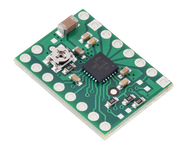
This breakout board for TI’s DRV8434S microstepping bipolar stepper motor driver operates from 4.5 V to 48 V and can deliver up to approximately 1.2 A continuous per phase without a heat sink or forced air flow (2 A peak). The SPI interface allows configuration of the current limit, step mode (11 step modes from full-step through 1/256-step), decay mode, and stall detection. The driver also features built-in protection against under-voltage, over-current, and over-temperature conditions. This version of the board uses an on-board potentiometer for setting the maximum current limit, and SPI can be used to set the actual current limit to intermediate values in increments of the set maximum/16.
Alternatives available with variations in these parameter(s): current limit control header pins soldered? Select variant…
 Compare all products in DRV8434x Stepper Motor Driver Carriers or
  16-pin Stepper Motor Drivers.
| Description | Specs (14) | Pictures (8) | Resources (8) | FAQs (4) | On the blog (1) | Distributors (38) |
|---|
- I want to control a 3.9 V, 600 mA bipolar stepper motor, but this driver has a minimum operating voltage above 3.9 V. Can I use this driver without damaging the stepper motor?
Yes. To avoid damaging your stepper motor, you want to avoid exceeding the rated current, which is 600 mA in this instance. All of our stepper motor drivers let you limit the maximum current, so as long as you set the limit below the rated current, you will be within spec for your motor, even if the voltage exceeds the rated voltage. The voltage rating is just the voltage at which each coil draws the rated current, so the coils of your stepper motor will draw 600 mA at 3.9 V. By using a higher voltage along with active current limiting, the current is able to ramp up faster, which lets you achieve higher step rates than you could using the rated voltage.
If you do want to use a lower motor supply voltage for other reasons, consider using our DRV8834 or STSPIN-220 low-voltage stepper motor drivers.
- Do I really need to set the current limit on my stepper motor driver before using it, and if so, how do I do it?
Yes, you do! Setting the current limit on your stepper motor driver carrier is essential to making sure that it runs properly. An appropriate current limit also ensures that your motor is not allowed to draw more current than it or your driver can handle, since that is likely to damage one or both of them.
For the DRV8434A Stepper Motor Driver Carrier the current limit is set by adjusting the board’s potentiometer. We strongly recommend using a multimeter to measure the VREF voltage while setting the current limit so you can be sure you set it to an appropriate value (just turning the pot randomly until things seem to work is not a good approach). The following video has more details on setting the current limit:
Setting the current limit on the DRV8434S SPI Stepper Motor Driver Carrier, 2A Max. Current Limit is done through its SPI interface (this is very different from most of our other stepper motor driver carriers, which have their current limits set through their on-board potentiometers). The DRV8434S SPI Stepper Motor Driver Carrier, 2A Max defaults to its maximum possible current limit setting on start-up, which is much more current than the board can safely deliver, so you will need to set the current limit to an appropriate value for your stepper motor before enabling the driver outputs to prevent damage to the board. This is done by adjusting the TRQ_DAC bits in the CTRL1 register. The DRV8434S datasheet has more information on how to set the current limit through the SPI interface, and our Arduino library includes example sketches showing how to implement this in software.
For the DRV8434S SPI Stepper Motor Driver Carrier, Potentiometer for Max Current Limit, the current limit can be adjusted through both the onboard potentiometer and SPI. If the TRQ_DAC scaling factor at its left at its default of 100%, the potentiometer can be used alone to set the current limit, like with the DRV8434A. Otherwise, the TRQ_DAC value set through SPI is used to further scale the current limit set with the potentiometer.
- My stepper motor driver is overheating, but my power supply shows it’s drawing significantly less than the continuous current rating listed on the product page. What gives?
- Measuring the current draw at the power supply does not necessarily provide an accurate measure of the coil current. Since the input voltage to the driver can be significantly higher than the coil voltage, the measured current on the power supply can be quite a bit lower than the coil current (the driver and coil basically act like a switching step-down power supply). Also, if the supply voltage is very high compared to what the motor needs to achieve the set current, the duty cycle will be very low, which also leads to significant differences between average and RMS currents: RMS current is what is relevant for power dissipation in the chip but many power supplies won’t show that. You should base your assessment of the coil current on the set current limit or by measuring the actual coil currents.
- How do I connect my stepper motor to a bipolar stepper motor driver?
- The answer to this question depends on the type of your stepper motor and how many wires it has. We have an application note that details possible methods for connecting stepper motors to bipolar drivers and controllers and the advantages and disadvantages of each option.


