Generic Linear Actuators »
Generic Linear Actuator with Feedback: 12" Stroke, 12V, 0.6"/s

This 12 V linear actuator has a load rating of 110 lbs (51 kg) and a maximum speed of 0.6 in/s (16 mm/s). Limit switches at each end make the actuator easy to control over its full range of motion, and the worm drive ensures that the shaft will hold its position even when unpowered. This version has a 12-inch stroke and a built-in potentiometer for position feedback.
Alternatives available with variations in these parameter(s): nominal stroke length feedback potentiometer included? linear speed @ 12V, no load Select variant…

| Description | Specs (7) | Pictures (6) | Resources (1) | FAQs (1) | On the blog (0) | Distributors (0) |
|---|
Overview
These low-cost linear actuators are 12V DC gearmotors that use a worm drive to move a shaft back and forth along its length. The worm drive ensures that the shaft will hold its position even when unpowered. Two limit switches safely stop the motor at either end of its range, while diodes allow it to reverse direction after reaching a limit point. The actuators are mostly metal, and the entire case is sealed to protect against dust and water (rated IP54).
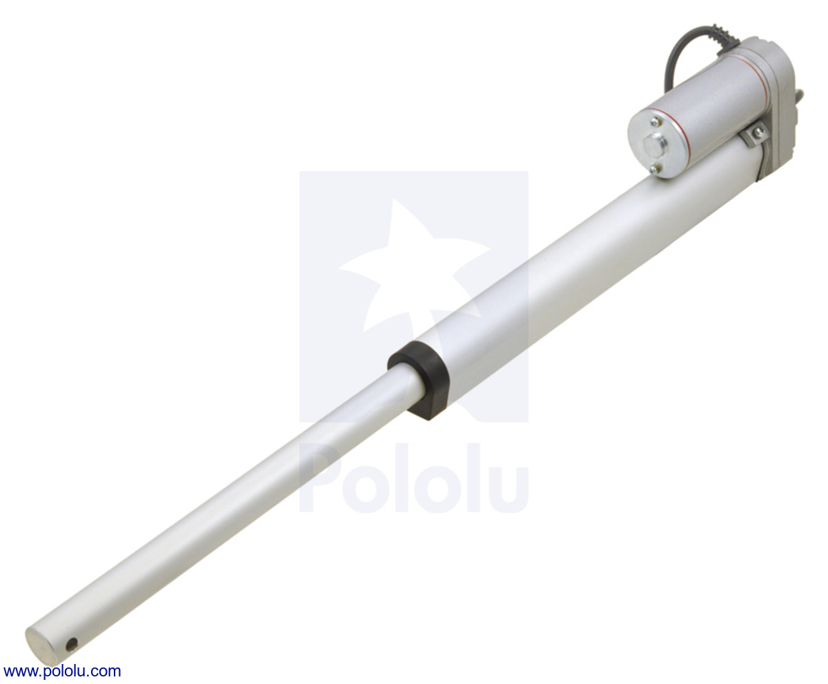 |
Generic linear actuator with 8″ stroke, fully extended. |
|---|
The linear actuators are available in a variety of lengths and with optional potentiometers that are linked to the shaft position, for use in feedback systems. They are also available in two speeds: 0.6″/s (16 mm/s) and 1.5″/s (40 mm/s). The slower 0.6″/s versions can exert a maximum force of about 110 lbs (500 N or 51 kg), while the faster 1.5″/s versions can exert up to 22 lbs (100 N or 10 kg).
You can use the table on our linear actuator category page to help you find the actuator with the combination of speed and force that best meets your project’s requirements.
Mounting brackets are available for attaching the actuators to a structure; two are required for each actuator.
 |
Bracket connected to one end of a generic linear actuator. |
|---|
Using the actuator
To test-drive the actuator, simply connect a power source of up to 12 V to the motor leads. Reversing the applied voltage will reverse the direction of motion. A motor controller or motor driver is required for electronic speed and direction control. We recommend our Jrk Motor Controllers for use with the feedback actuators and the Pololu Simple Motor Controller 18v7 for controlling the actuators without feedback, though many of our other motor controllers and motor drivers are capable of powering this actuator.
These actuators have a stall current of 7 A at 12 V, but they will, on average, draw far less than this when used within their load ratings. They draw around 1 A with no load and approximately 3 A at their maximum rated load, so we have found they generally work well with our lower-power jrk 21v3 motor controller with feedback (see the bottom of this page for more information using this controller for closed-loop linear actuator position control). Note, however, that the actuators can briefly draw close to their full stall current when abruptly started or on a sudden change of direction. Such current spikes can be dampened if you take steps to limit the acceleration of the actuator (many of our motor controllers offer optional acceleration limiting).
Dimensional drawings
Diagrams of the linear actuators are shown below. Please note that the actuator stroke lengths in inches are nominal; the actual dimensions are specified in millimeters. The versions that include potentiometers have a larger gearbox, so their overall size and weight is larger.
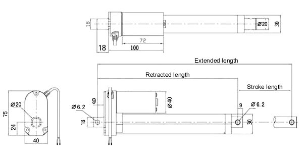 |
Dimensions (in mm) of the generic linear actuators without feedback. |
|---|
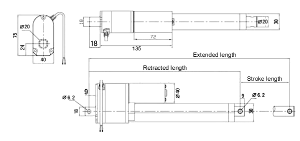 |
Dimensions (in mm) of the generic linear actuators with feedback. |
|---|
| Stroke length | Without feedback | With feedback | ||
|---|---|---|---|---|
| Retracted length |
Extended length |
Retracted length |
Extended length |
|
| 100 mm (~4″) | 205 mm | 305 mm | 240 mm | 340 mm |
| 200 mm (~8″) | 305 mm | 505 mm | 340 mm | 540 mm |
| 300 mm (~12″) | 405 mm | 705 mm | 440 mm | 740 mm |
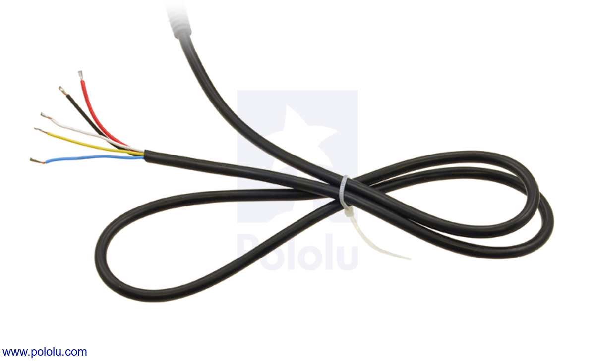
Actuator leads
Each actuator has a 3-foot-long cable. Actuators without feedback have two unterminated, stripped power leads as shown in the left picture below. On actuators with feedback, the cable includes three additional potentiometer leads as shown in the right picture below. The potentiometer has an end-to-end resistance of 10 kΩ; the yellow and white leads are connected to its end terminals, while the blue lead is connected to its wiper. The resistance between the blue and white leads increases as the actuator extends.
|
|

Using a jrk motor controller with a linear actuator with feedback
The feedback feature included with our jrk motor controllers make them a great solution for precisely controlling our linear actuators with feedback. Our settings file for the jrk configuration utility makes setup easy, eliminating the need to calibrate the feedback and tune the PID constants. To get started, follow the steps below:
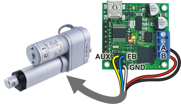 |
Connecting a linear actuator with feedback to a Jrk 21v3 motor controller. |
|---|
- If you have not already, read through the Jrk USB Motor Controllers User’s Guide and download its drivers and configuration software.
- Connect your jrk to a PC with a USB cable and launch the configuration utility. The red LED should be on, and the green LED should be flickering quickly.
- Download the jrk 21v3 settings file for linear actuators (1k txt). The settings in this file work with any length actuator that has a feedback potentiometer, and they were tested on the jrk 21v3, which is powerful enough to drive these actuators in typical applications. These settings should also mostly work for the higher-power jrk 12v12, though a few of them (e.g. current calibration) might need to be adjusted.
- In the configuration utility, choose File → Open settings file (Ctrl + O), and navigate to the location of the settings file you downloaded in step 2.
- Click on the PID tab of the configuration utility and verify that the proportional and derivative coefficients are not zero. If they are zero, the settings file was probably not loaded properly and you should try performing the previous step again.
- With your power supply off, connect your linear actuator to your jrk using the connections shown in the picture to the right. The picture shows a jrk 21v3, but the connections will be the same if you use a jrk 12v12.
- Turn on Power.
- On the Error tab, choose “Clear Errors”. The “No power” and “Feedback disconnect” errors will clear. The red LED will turn off, and the yellow LED will blink slowly.
- On the Input tab choose “Set Target” to move your actuator to the target position.
While this setting file gives precise control over most of an actuator’s range, you might find decreased performance very near the extremes due to the limit switches. The voltage range covered by the potentiometer also varies among different actuators. If your project requires better control, you might need to recalibrate the feedback settings for your particular actuator.
Related products


Home | Forum | Blog | Support | Ordering Information | Lists | Distributors | BIG Order Form | About | Contact
© 2001–2026 Pololu Corporation
