Support » Pololu Motoron Motor Controller User’s Guide » 4. Pinout »
4.2. Motoron M1U550, M2U550, M1U256 and M2U256 pinout
<table class="side_by_side_pics">
<tr>
<td><table class="picture_with_caption center"><tr><td style="max-width: 251px"><a href="https://a.pololu-files.com/picture/0J12138.1200.jpg?18c19c4b1976d7c7917cdd0619db1611" class="noscript-fallback"><img alt="" class="zoomable" data-gallery-pictures="[{"id":"0J12138","caption":"\u003cp\u003eMotoron M1U550 Single Serial Motor Controller pinout.\u003c/p\u003e","url_tiny":"https://a.pololu-files.com/picture/0J12138.98x98.jpg?18c19c4b1976d7c7917cdd0619db1611","url_medium":"https://a.pololu-files.com/picture/0J12138.600x480.jpg?18c19c4b1976d7c7917cdd0619db1611","url_full":"https://a.pololu-files.com/picture/0J12138.1200.jpg?18c19c4b1976d7c7917cdd0619db1611","longest_side":1199}]" data-picture-id="0J12138" data-picture-longest_side="1199" src="https://a.pololu-files.com/picture/0J12138.251.jpg?18c19c4b1976d7c7917cdd0619db1611" /></a></td></tr><tr><th style="max-width: 251px"><p>Motoron M1U550 Single Serial Motor Controller pinout.</p></th></tr></table></td>
<td><table class="picture_with_caption center"><tr><td style="max-width: 251px"><a href="https://a.pololu-files.com/picture/0J12140.1200.jpg?74da74f57d1a7124bb7d3ebcee9216c6" class="noscript-fallback"><img alt="" class="zoomable" data-gallery-pictures="[{"id":"0J12140","caption":"\u003cp\u003eMotoron M2U550 Dual Serial Motor Controller pinout.\u003c/p\u003e","url_tiny":"https://a.pololu-files.com/picture/0J12140.98x98.jpg?74da74f57d1a7124bb7d3ebcee9216c6","url_medium":"https://a.pololu-files.com/picture/0J12140.600x480.jpg?74da74f57d1a7124bb7d3ebcee9216c6","url_full":"https://a.pololu-files.com/picture/0J12140.1200.jpg?74da74f57d1a7124bb7d3ebcee9216c6","longest_side":1200}]" data-picture-id="0J12140" data-picture-longest_side="1200" src="https://a.pololu-files.com/picture/0J12140.251.jpg?74da74f57d1a7124bb7d3ebcee9216c6" /></a></td></tr><tr><th style="max-width: 251px"><p>Motoron M2U550 Dual Serial Motor Controller pinout.</p></th></tr></table></td>
</tr>
<tr>
<td><table class="picture_with_caption center"><tr><td style="max-width: 251px"><a href="https://a.pololu-files.com/picture/0J11946.1200.jpg?22190e80d23fa62a8a2885a9302c56bf" class="noscript-fallback"><img alt="" class="zoomable" data-gallery-pictures="[{"id":"0J11946","caption":"\u003cp\u003eMotoron M1U256 Single Serial Motor Controller pinout.\u003c/p\u003e","url_tiny":"https://a.pololu-files.com/picture/0J11946.98x98.jpg?22190e80d23fa62a8a2885a9302c56bf","url_medium":"https://a.pololu-files.com/picture/0J11946.600x480.jpg?22190e80d23fa62a8a2885a9302c56bf","url_full":"https://a.pololu-files.com/picture/0J11946.1200.jpg?22190e80d23fa62a8a2885a9302c56bf","longest_side":1200}]" data-picture-id="0J11946" data-picture-longest_side="1200" src="https://a.pololu-files.com/picture/0J11946.251.jpg?22190e80d23fa62a8a2885a9302c56bf" /></a></td></tr><tr><th style="max-width: 251px"><p>Motoron M1U256 Single Serial Motor Controller pinout.</p></th></tr></table></td>
<td><table class="picture_with_caption center"><tr><td style="max-width: 251px"><a href="https://a.pololu-files.com/picture/0J11820.1200.jpg?5872b23a092c371a1fc0a9f303ecc80a" class="noscript-fallback"><img alt="" class="zoomable" data-gallery-pictures="[{"id":"0J11820","caption":"\u003cp\u003eMotoron M2U256 Dual Serial Motor Controller pinout.\u003c/p\u003e","url_tiny":"https://a.pololu-files.com/picture/0J11820.98x98.jpg?5872b23a092c371a1fc0a9f303ecc80a","url_medium":"https://a.pololu-files.com/picture/0J11820.600x480.jpg?5872b23a092c371a1fc0a9f303ecc80a","url_full":"https://a.pololu-files.com/picture/0J11820.1200.jpg?5872b23a092c371a1fc0a9f303ecc80a","longest_side":1200}]" data-picture-id="0J11820" data-picture-longest_side="1200" src="https://a.pololu-files.com/picture/0J11820.251.jpg?5872b23a092c371a1fc0a9f303ecc80a" /></a></td></tr><tr><th style="max-width: 251px"><p>Motoron M2U256 Dual Serial Motor Controller pinout.</p></th></tr></table></td>
</tr>
</table>
<p>
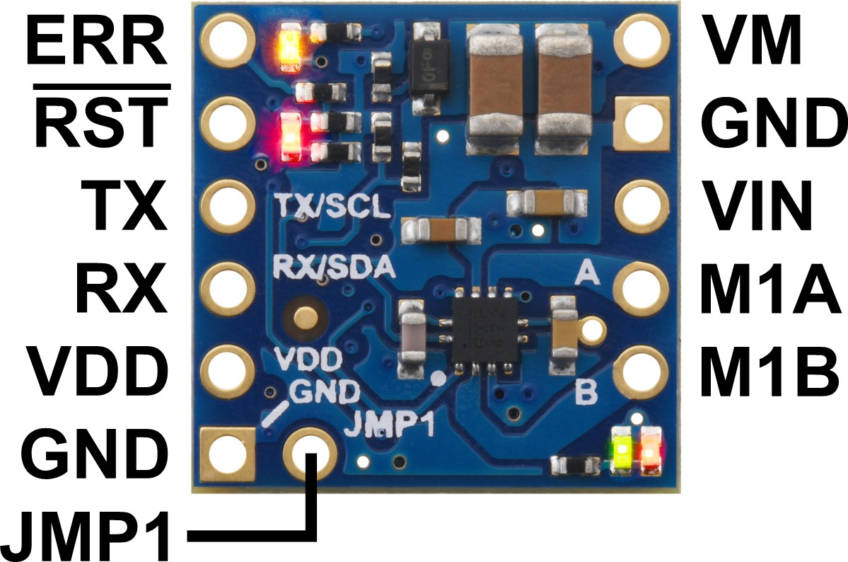
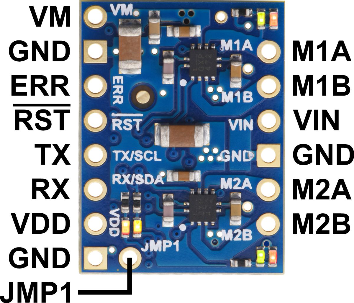
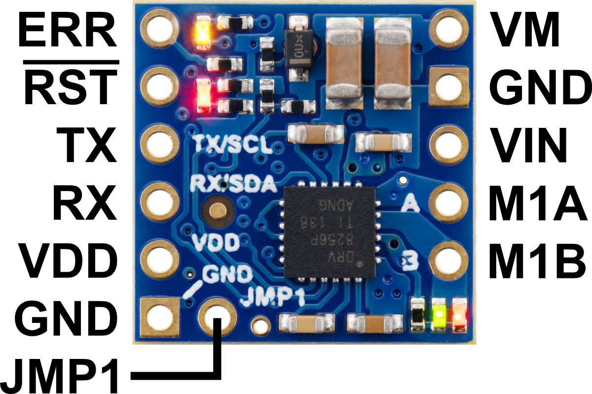
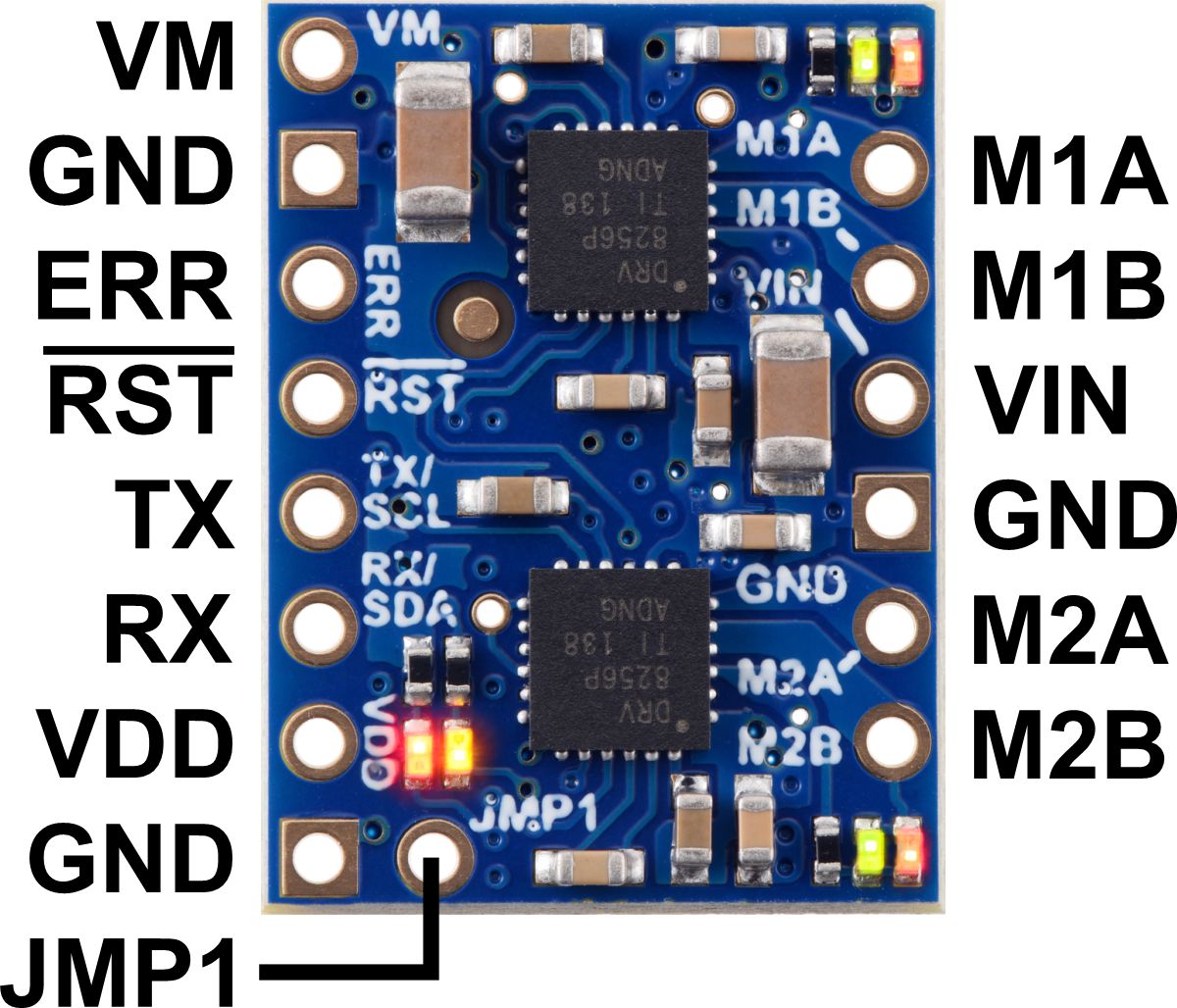
The diagrams above identify the control and power pins on the Motoron M1U550, M2U550, M1U256 and M2U256. <a href="/docs/0J84/3.2.2">Section 3.2.2</a> explains how to connect motor power, motors, and a microcontroller.</p>
<p>The motor power supply should be connected to the <strong>VIN</strong> pin and adjacent <strong>GND</strong> pin, and a motor can be connected to each pair of <strong>MxA</strong> and <strong>MxB</strong> pins (e.g. M1A and M1B). For more information on choosing a power supply and motors, see <a href="/docs/0J84/3.1">Section 3.1</a>.</p>
<p>The Motoron’s logic is powered from the <strong>VDD</strong> pin, and it is controlled via UART serial through the <strong>TX</strong> and <strong>RX</strong> pins (see <a href="/docs/0J84/7">Section 7</a>). Additional <strong>GND</strong> pins provide a common ground reference between the Motoron and device controlling it.</p>
<p>The <strong>VM</strong> pin provides access to the reverse-protected motor supply voltage.</p>
<p>The <strong>ERR</strong> pin drives high when the red LED is on, which usually indicates an error as described in <a href="/docs/0J84/5">Section 5</a>. The ERR pin is protected by a 220Ω series resistor. When the red LED is not on, the ERR pin is pulled down weakly.</p>
<p>The <strong><span class="overline">RST</span></strong> pin can be driven low to reset the Motoron; see <a href="/docs/0J84/12">Section 12</a> for more details.</p>
<p>The <strong>JMP1</strong> pin can be shorted to the adjacent GND pin to allow the Motoron’s serial settings to be changed, as detailed in <a href="/docs/0J84/3.6">Section 3.6</a>. Also, shorting JMP1 to GND at startup causes the Motoron to ignore the serial settings configured in EEPROM and use safe default settings instead (see <a href="/docs/0J84/10">Section 10</a>).</p>