Support » Pololu Motoron Motor Controller User’s Guide »
7. Serial interface
To control the Motoron M1U550, M2U550, M1U256 or M2U256, you will need to use the Motoron’s UART serial interface.
The RX and TX pins of the Motoron provide its serial interface. The Motoron’s RX pin is an input, and its TX pin is an output. The RX pin has a weak pull-up resistor, and each pin is protected by a 220Ω series resistor.
Serial voltage levels
The UART serial interface uses non-inverted TTL logic levels: a level of 0 V corresponds to a value of 0, and a level of VDD corresponds to a value of 1. The input signal on RX must be below 0.3×VDD to be recognized as low, and above 0.7×VDD to recognized as high. The voltage on RX must not exceed VDD by more than 0.3 V. Therefore, if the Motoron is running at 3.3 V, its RX pin is not 5 V tolerant.
Serial data format
The data format is 8 data bits, one stop bit, with no parity, which is often expressed as 8-N-1. The diagram below depicts a typical serial byte:
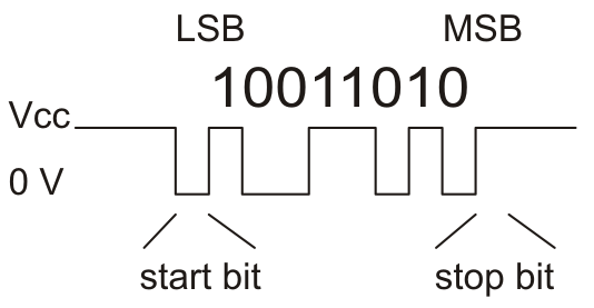 |
Diagram of a non-inverted TTL serial byte. |
|---|
Serial baud rate
The UART serial interface is asynchronous, meaning that the sender and receiver each independently time the serial bits. The sender and receiver must be configured to use the same baud rate, which is typically expressed in bits per second.
By default, the Motoron uses 115200 baud. The baud rate is stored in the Motoron’s non-volatile EEPROM memory, and you can change it by sending a “Write EEPROM” command. If the JMP1 pin is shorted to GND at startup, the Motoron will ignore the baud rate in EEPROM and use 9600 baud instead. The Motoron determines what baud rate to use when it starts up, so any changes to the JMP1 pin or the EEPROM will not take effect until the next reset.
The Motoron supports baud rates from 300 to 250000 bps. It is possible to configure the Motoron to use baud rates up to 1 Mbps, but there are two potential problems with high baud rates. First of all, if the Motoron receives a rapid stream of commands using a baud rate higher than 115200, there is a risk that the Motoron firmware might not process the commands fast enough and eventually start discarding data (this condition is called a software overrun and can be detected). Secondly, the Motoron can only generate baud rates of the form 16 Mbps divided by an integer, so baud rates faster than 115200 baud cannot always be accurately generated.
Serial command protocols
The Compact protocol is the simpler and more compact of the two protocols supported by the Motoron. It is the protocol you should use if the Motoron is the only device connected to your serial line. A compact protocol command consists of a command byte with its most-significant byte set followed by the data bytes needed for the command (if there are any), each of which has its most-significant bit cleared. The Command reference section documents the specific bytes you need to send for a compact protocol command. You also need to append a cyclic redundancy check byte at the end of the command unless you have disabled CRC for commands.
The Pololu protocol can be used in situations where you have multiple devices connected to your serial line. This protocol is compatible with the serial protocol used by our other serial motor and servo controllers. As such, you can daisy-chain a Motoron on a single serial line along with our other serial controllers (including additional serial Motorons) and use the Pololu protocol to send commands specifically to the designated Motoron without confusing other devices on the line. Any compact protocol command can be transformed into a Pololu protocol command using the following process: first, clear the most significant bit of the command byte (the first byte). For example, the command byte of a normal “Set speed” command is 0xD1, and it becomes 0x51 in the Pololu protocol. Next, insert at the beginning of the command a 0xAA byte followed by a byte between 0 and 127 that specifies the device number of the Motoron you want to address. Unless you have disabled CRC for commands, you need to append a CRC byte at the end of the command and it must be calculated over the entire Pololu protocol command, including the first two bytes.
The Motoron’s device number is 16 by default. The device number is stored in the Motoron’s non-volatile EEPROM memory, and you can change it by sending a “Write EEPROM” command. If the JMP1 pin is shorted to GND at startup, the Motoron will ignore the device number in EEPROM and use 15 instead. The Motoron determines what device number to use when it starts up, so any changes to the JMP1 pin or the EEPROM will not take effect until the next reset.
You do not need to configure the Motoron ahead of time to use a specific protocol: the Motoron will detect what protocol you are using from the first byte of your command.
The Motoron can be configured to respond to an alternative device number. If the alternative device number is enabled, the Motoron will respond to commands that are addressed to either the primary device number or the alternative device number. This can be useful if you want to assign your Motorons to groups and send a single command to all the Motorons in a group, while still being able to individually address each Motoron.
Communication option: 14-bit responses
The Motoron can be configured to use a 14-bit device number. With this option enabled, the device numbers can range from 0 to 16383, instead of the typical range of 0 to 127. After the 0xAA byte, you have to send two device number bytes, both of which are between 0 and 127: the first byte holds the lower 7 bits of the device number, while the second byte holds the upper 7 bits of the device number. The format of the “Multi-device error check” and “Multi-device write” commands also change when this option is enabled.
Communication option: 7-bit responses
In general, the data sent by the Motoron in response to serial commands is arbitrary binary data: the bytes can be anything from 0 to 255. The Motoron’s 7-bit responses option causes it to encode those responses in a format that only uses values from 0 to 127. This can be useful if you have wired your Motorons in such a way that the responses from one Motoron will be seen by another Motoron, and you do not want those responses to accidentally be interpreted as commands.
The 7-bit encoding performed by the Motoron works as follows. First, if the serial response is longer than 7 bytes, the Motoron truncates it to be exactly 7 bytes long, throwing away all the bytes after the first 7. This behavior might change in future firmware versions, so we recommend that you do not request more than 7 bytes from the Motoron if you have enabled 7-bit responses. Next, the Motoron sets the most-significant bit of each byte in the response to 0. The Motoron packs the former values of those most significant bits (MSbs) into a single byte and appends it to the response. The bits of that final byte are in the same order as the bytes they correspond to: the least significant bit corresponds to the first byte, while the next bit corresponds to the second byte, and so on. The Motoron does this conversion before it computes and appends the (optional) CRC byte for the response.
Communication option: ERR is DE
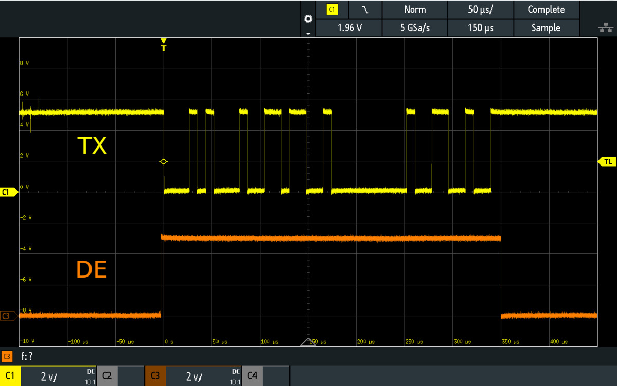 |
Oscilloscope trace showing the ERR/DE pin of the Motoron M2U256 driving high while its TX pin sends data. |
|---|
The Motoron’s ERR pin can be configured to act as a driver enable (DE) line. When the ERR is DE option is enabled, instead of indicating errors as described in Section 5, the ERR pin will drive high while the Motoron is transmitting serial data on its TX pin and drive low at other times. This feature is intended to be used in RS-485 systems where the ERR pin is connected to the driver enable (DE) pin of an RS-485 transceiver. The Motoron’s red LED is tied to the ERR pin, so its will briefly blink whenever the Motoron transmits a serial response.
Response delay
The Motoron’s Response delay setting specifies an additional delay that the Motoron will perform before sending a serial response. This can be useful in systems where another device is reading data from the Motoron and needs some time to switch from transmitting to receiving. The setting is 0 by default, and can be as large as 255 µs, with 1 µs resolution.
Configuring the UART serial interface
You can change the Motoron’s UART serial settings by following the instructions in Section 3.6. Alternatively, write your own code that use the “Write EEPROM” command documented in Section 9. The encoding of the serial settings in EEPROM is documented in Section 10.
Related products


Related categories


Home | Forum | Blog | Support | Ordering Information | Lists | Distributors | BIG Order Form | About | Contact
© 2001–2026 Pololu Corporation
