Support » Pololu 3pi+ 2040 User’s Guide » 6. The 3pi+ 2040 in detail »
6.2. User interface
|
|
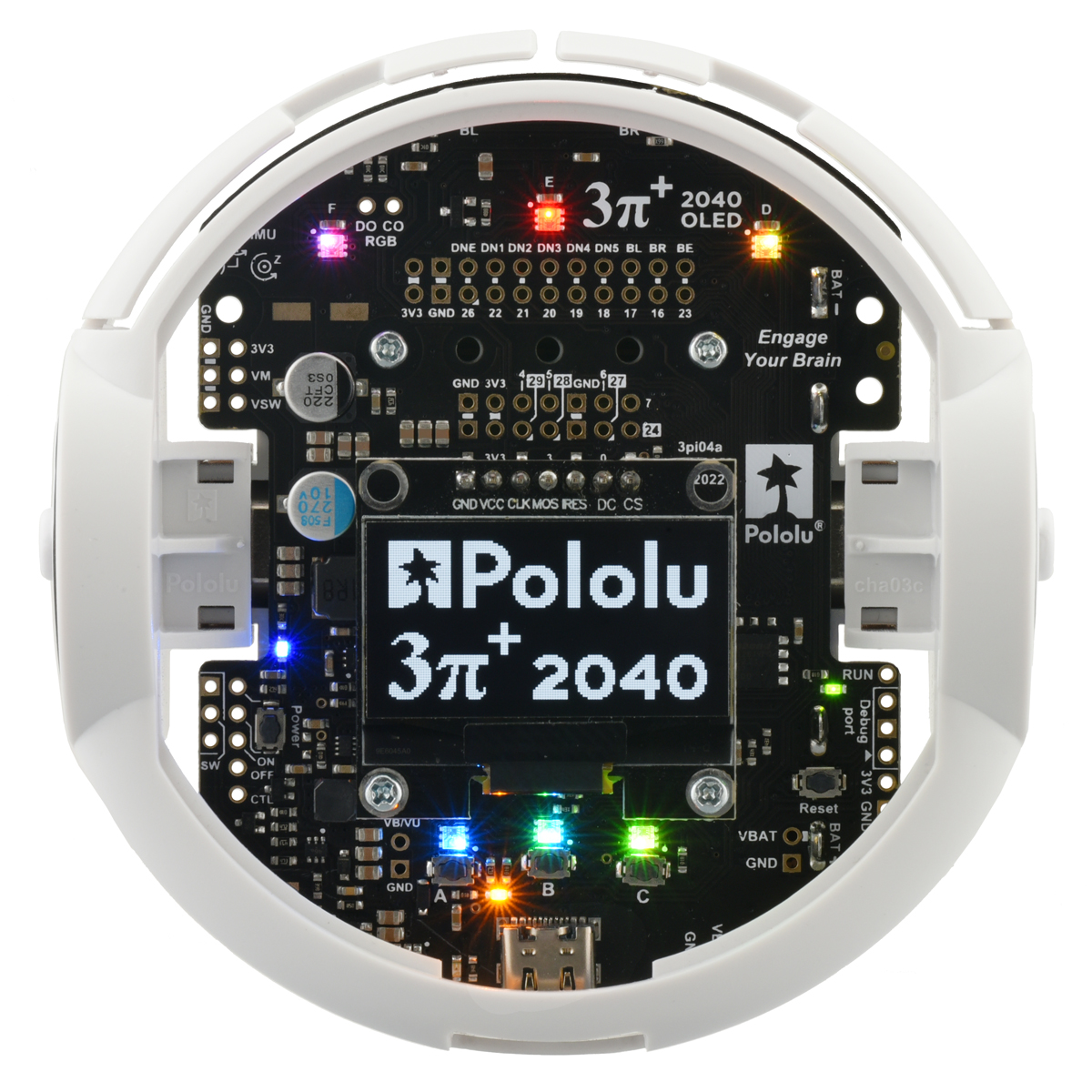
Pushbuttons
The 3pi+ 2040 control board has five pushbuttons: a power button on the left, a reset button on the right, and three user pushbuttons located along the rear. Pressing the reset button connects the RUN pin to ground, and pressing one of the user pushbuttons pulls the associated I/O pin to ground through a resistor. The user pushbuttons, labeled A, B, and C, are on GP25, QSPI_SS_N, and GP0, respectively. Button B doubles as a BOOTSEL button to run the RP2040’s built-in USB bootloader if held on startup.
The three buttons’ I/O lines are also used for other purposes: GP0 is a display interface line, GP25 controls the yellow user LED, and QSPI_SS_N is the flash memory chip select pin (in addition to its BOOTSEL function). These uses require the pins to be driven by the RP2040, and reading QSPI_SS_N is not as straightforward as reading a normal GPIO pin. However, resistors in the button circuits ensure that the 3pi+ 2040 control board will not be damaged and operation will not be disrupted even if the buttons are pressed while the corresponding pins are being driven, and the functions in the 3pi+ 2040 Robot Libraries and Example Code take care of configuring the pins, reading and debouncing the buttons, and restoring the pins to their original states.
Indicator LEDs
The 3pi+ 2040 control board has six indicator LEDs, one of which is user-controllable:
- A yellow user LED is connected to GP25. You can drive this pin low in a user program to turn this LED on. The user LED is located near the USB connector at the rear of the board, and the 3pi+ 2040 libraries contain functions that make controlling it easier. The user LED shares the GP25 pin with button A.
The remaining five LEDs are power indicators:
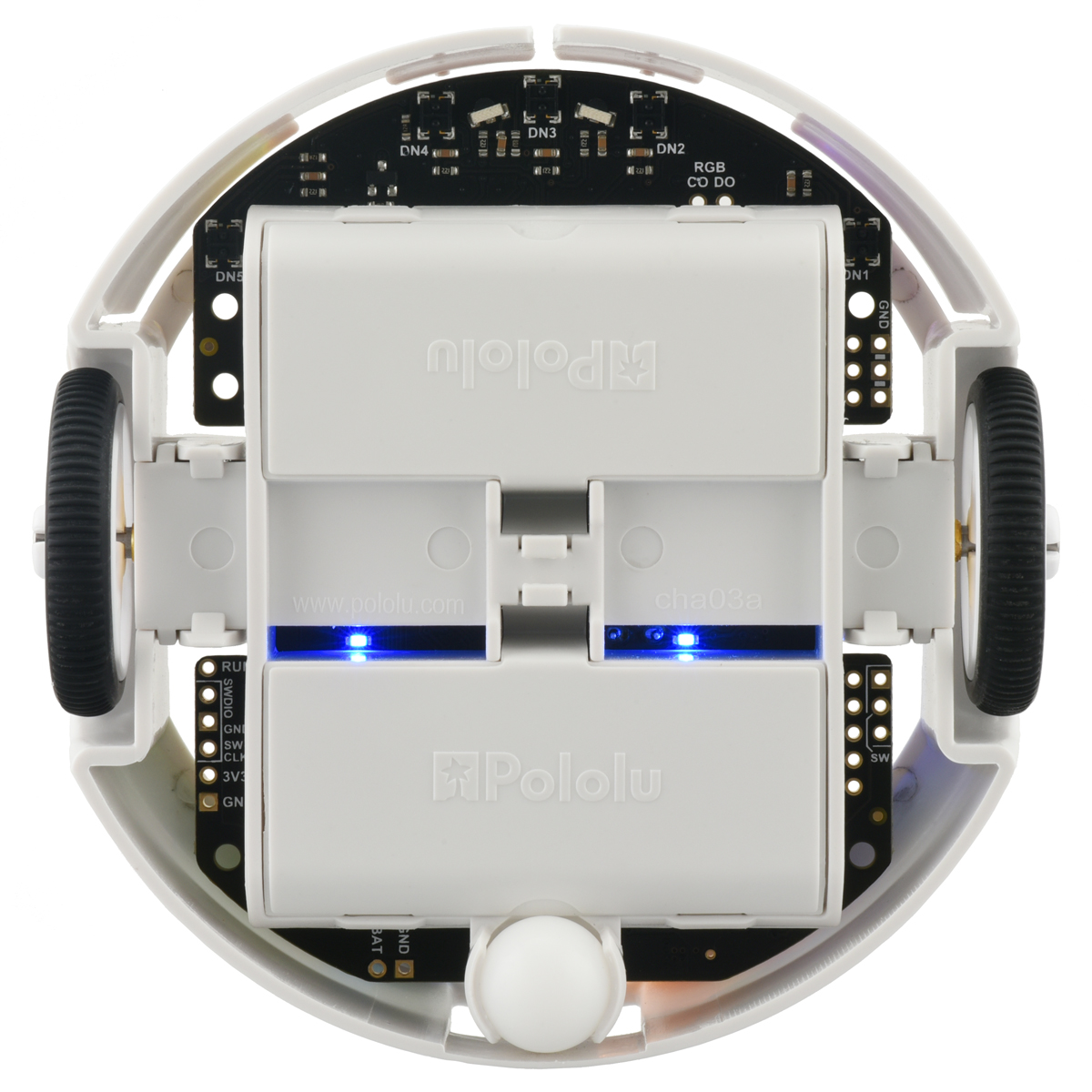
- A blue power LED next to the power button indicates when the motor voltage regulator is active and producing 8 V (VM). The regulator is powered by the 3pi+’s batteries, so the power switching circuit must be turned on.
- A blue power LED on the left underside of the 3pi+ (closer to the power button) indicates when the logic boost regulator is active and producing 8.3 V (VBST). The regulator is powered by the 3pi+’s batteries, so the power switching circuit must be turned on.
- A blue power LED on the right underside of the 3pi+ (farther from the power button) indicates when the 3pi+’s 3.3 V logic buck regulator is receiving power (VB/VU). The input to the 3.3 V regulator can come from either the 8.3 V boost regulator or from USB, so this LED will be lit when either the power switching circuit is turned on or when the 3pi+ is plugged in to USB.
- A green power LED next to the USB connector indicates when the USB bus voltage (VBUS) is present.
- A green power LED near the reset button indicates when the 3pi+’s logic circuit, including the microcontroller, is receiving 3.3 V power (3V3).
RGB LEDs
The 3pi+ 2040 control board also features six individually-addressable RGB LEDs. Three of these are near the rear of the board by the pushbuttons, while the other three are along the front of the board. The RGB LEDs have integrated drivers compatible with the popular APA102 addressable LED, and they are chained together in alphabetical order (labeled A through F) and arranged counterclockwise on the board.
The control board uses SPI0, one of its two hardware SPI modules, on GP3 and GP6 (TX and SCK, respectively) to control the RGB LEDs. The 3pi+ 2040 libraries include functions that make it easier to control the RGB LEDs and use them together with the OLED display, which shares the SPI0 interface with the RGB LEDs. The display and RGB LEDs share a common pin for SPI0 TX (data), but use different pins for SPI0 SCK (clock), allowing them to be controlled separately.
The output signals from the last RGB LED are brought out to the DO (data out) and CO (clock out) pins, and you can use these pins to add more APA102-compatible RGB LEDs to the chain.
Buzzer
The buzzer included with the 3pi+ 2040 control board can be soldered into the designated through-holes and used to generate simple sounds and music (the buzzer is pre-installed on the assembled versions of the robot). By default, it is connected to GP7, which can be configured as PWM3 B to produce hardware pulse width modulation. If you alternate between driving the buzzer pin high and low at a given frequency, the buzzer will produce sound at that frequency. You can play notes and music with the buzzer using functions in the 3pi+ 2040 libraries. If you want to use GP7 for an alternate purpose, you can disconnect the buzzer circuit by cutting the surface-mount jumper next to the buzzer.
Display header
The 3pi+ 2040 control board has a 1×7 header where you can connect a graphical OLED module with a low-profile male header. The kit and assembled versions of the 3pi+ 2040 robot include an OLED display that has a resolution of 128×64 pixels and uses an SH1106 controller (1MB pdf), which the 3pi+ communicates with via its SPI0 module.
The 3pi+ 2040 libraries provide functions to show data on a connected display while also allowing the display interface lines to be used for other purposes (such as pushbutton inputs and RGB LED data).
Related products


Home | Forum | Blog | Support | Ordering Information | Lists | Distributors | BIG Order Form | About | Contact
© 2001–2026 Pololu Corporation
