Support » Pololu Motoron Motor Controller User’s Guide » 3.2. Connecting everything »
3.2.3. Connecting a Motoron shield for Arduino
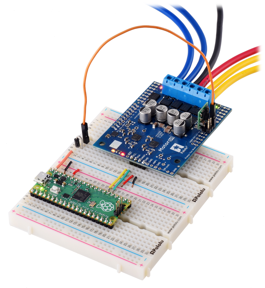
This section explains how to connect motor power, motors, and a microcontroller to the Motoron M3S550, M3S256 and the M2S family, which are designed to be shields for an Arduino.
Connecting terminal blocks
For the Motoron M3S550 and M3S256, we generally recommend using green 3.5mm-pitch terminal blocks for the motor power and motor connections. If you have an assembled version of the Motoron, these terminal blocks come soldered to the board. Otherwise, you will need to solder them yourself. They should be soldered to the larger through holes for board power and motor outputs (GND, VIN, M1A, M1B, M2A …).
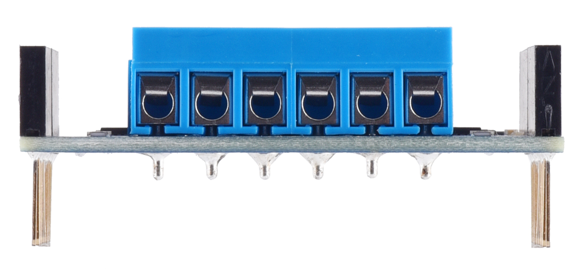
You can use blue 5mm-pitch terminal blocks if your current requirements are not too high and you can ensure that there is adequate spacing between any stacked boards in your system to prevent short circuits. This type of terminal block is included with the Motoron M3S550, M3S256, and M2S kit versions and comes soldered to the fully assembled versions of the Motoron M2S controllers. The 5mm blue terminal blocks are rated for 16 A so for higher-current applications we recommend soldering thick wires directly to the board. If you decide to use the 5mm terminal blocks, we recommend using the tabs on the side of the terminal blocks to connect them together before soldering them to the Motoron (see our video about how to install terminal blocks for more information).
We recommend only using the 5mm blue terminal blocks on Motoron shields that are at the top of a stack. Using those terminal blocks on two adjacent boards in a stack is likely to cause short circuits because they are taller than the headers.
|
|
Connecting motor power and motors
|
|
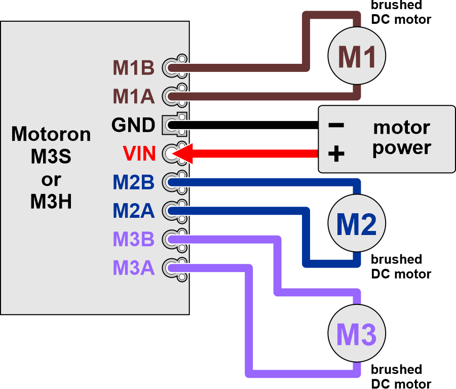
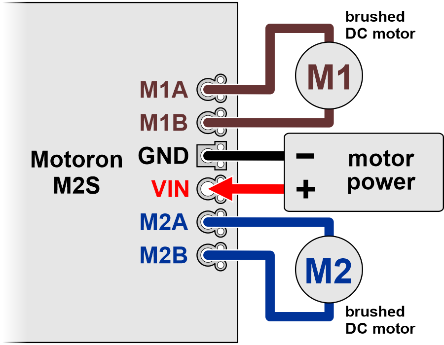
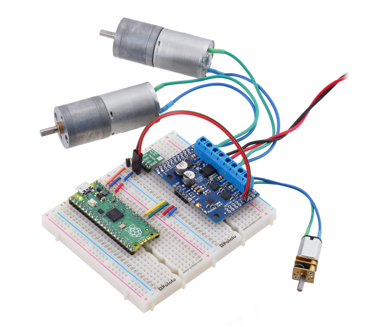
The negative terminal of the motor power supply should be connected to the Motoron’s large GND pin or the smaller pins next to it. The positive terminal of the motor power supply should be connected to the Motoron’s large VIN pin or the smaller pins next to it. These GND and VIN connections are required for each Motoron in a stack of Motorons. Connecting two Motorons via stackable headers does not connect their VIN pins at all, and it does not connect their GND pins in a way that is meant to carry the large currents involved in motor control. Note that connecting power to VIN does not power the Motoron’s microcontroller and does not cause any LEDs to turn on.
Each motor should have one lead connected to an MxA pin (M1A, M2A, or M3A) and the other lead connected to the MxB pin with the matching motor number. The Motoron’s concept of “forward” corresponds to MxA driving high while MxB drives low, so you might consider this when deciding which motor lead connects to which Motoron pin. You can also flip the wires later if you want to flip the direction of motion.
Connecting a controller
|
|
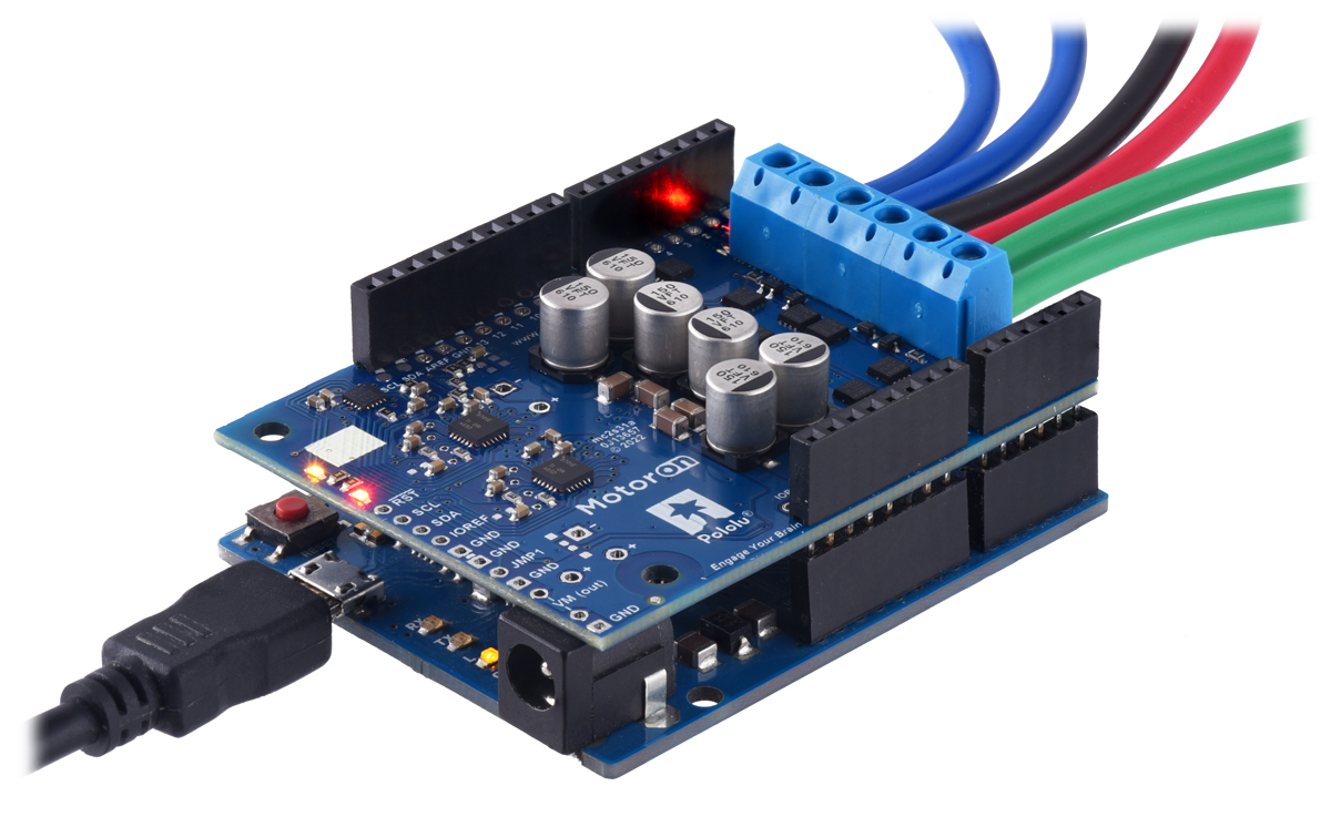
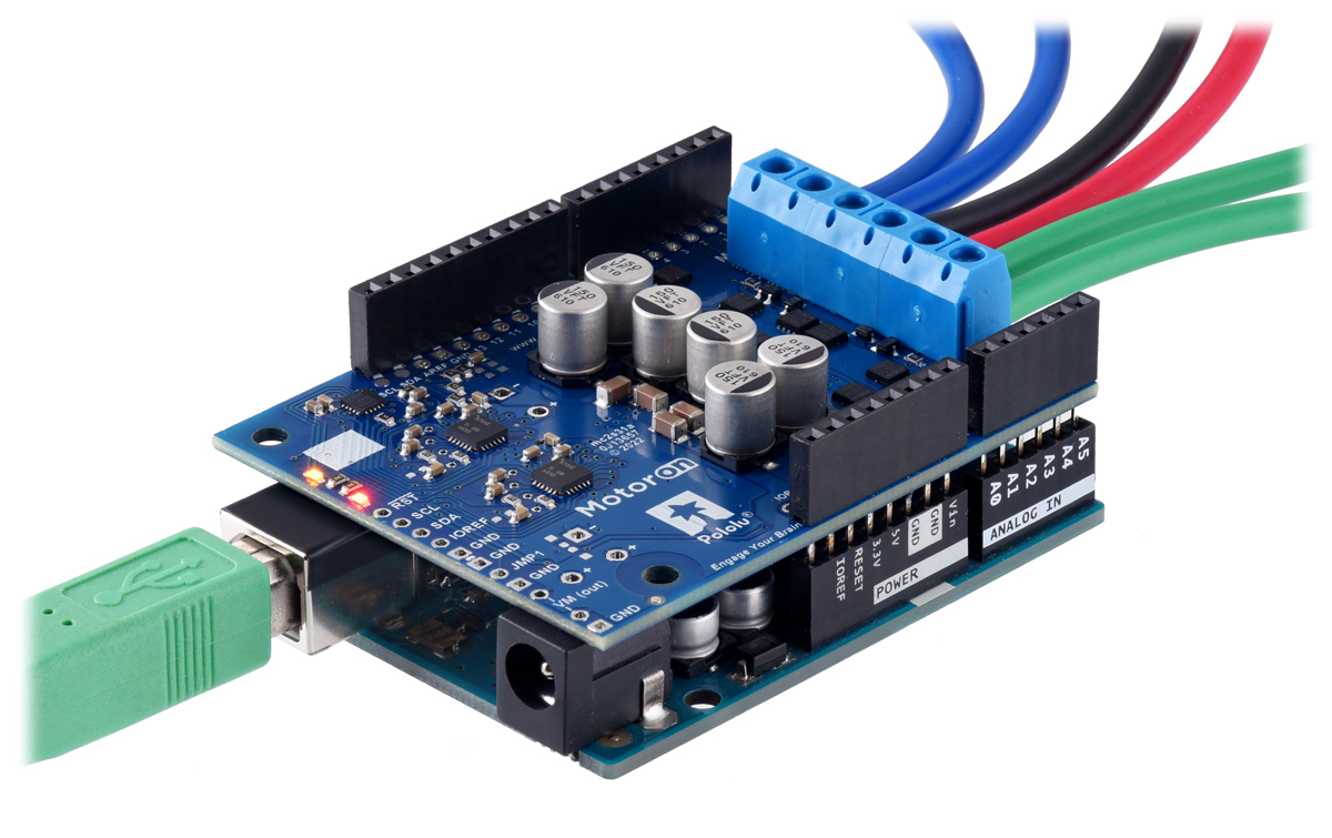
The Motoron shields for Arduino are designed to be plugged into the female headers of an Arduino or Arduino-compatible board that has the shape of the Arduino Leonardo or Arduino Uno R3 using stackable female headers or male headers soldered to the Motoron.
Plugging the Motoron into a controller this way connects the GND, SDA, and SCL pins of both boards, allowing the Arduino to communicate with the Motoron via I²C. It also powers the Motoron’s microcontroller from the Arduino’s IOREF pin. For most Motoron shields, the Motoron’s logic voltage (which powers the microcontroller) comes directly from IOREF. On the Motoron M3S550 shield, the IOREF pin supplies power to a 3.3 LDO regulator and the output of that regulator is the logic voltage.
 |
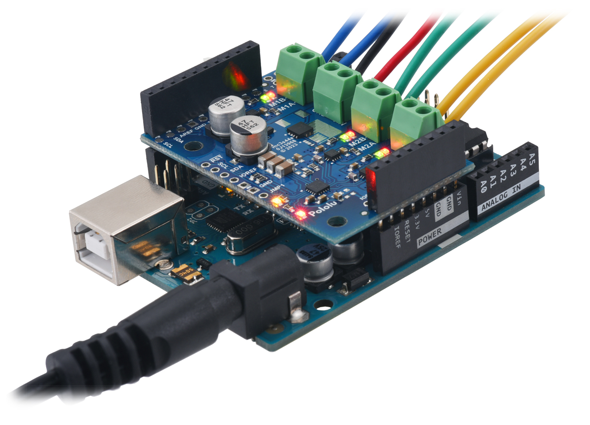
Motoron M2S shield being controlled by an Arduino Uno. Electrical tape is used on the USB Type-B connector to help prevent shorts. |
|---|
If you plug a Motoron M2S shield directly into an Arduino Uno or similar board, the tall USB connector can touch the Motoron and potentially cause a short circuit. Although that part of the Motoron M2S shield is protected by an insulating solder mask, we recommend adding electrical tape to the top of the USB connector to protect against this, as shown above.
The Motoron does not need to be connected directly to the Arduino: it can be connected through another shield (including other Motoron shields) as long as those boards pass the GND, SCL, SDA, and logic voltage connections through.
You can also connect the Motoron to a controller board that has a different shape as long as you make the same connections. The Motoron’s GND, SCL, and SDA pins should be connected to the corresponding pins on the controller board, and IOREF should be connected to the logic voltage supply of the controller board (the allowable logic voltage range can be found in the specifications for your particular Motoron).
|
|
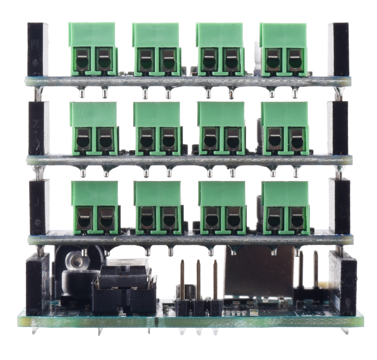
After you have connected one Motoron shield to a controller, you can connect other Motoron shields to the same controller simply by stacking them above or below the first one.
Once you make the GND and logic power connections and turn on the logic power, you should see the Motoron’s yellow LED blink. The red LED will also turn on unless something is communicating with the Motoron and causing it to turn the LED off.
Powering the Arduino
By default, the Motoron does not supply power to the Arduino, so you will need to power your Arduino separately. However, there are options for powering the controllers, as documented in Section 4.3 for the M3S550/M3S256 and Section 4.5 for the M2S shields.
Related products


Related categories


Home | Forum | Blog | Support | Ordering Information | Lists | Distributors | BIG Order Form | About | Contact
© 2001–2025 Pololu Corporation
