Support » Pololu Romi 32U4 Control Board User’s Guide »
4. Assembling the Romi 32U4 Control Board
Control board additions
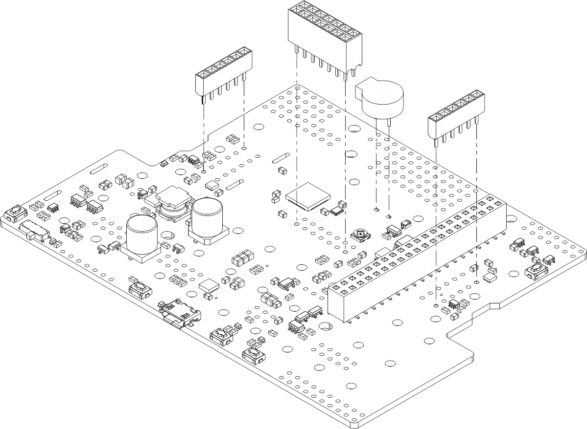
Most of the hardware on the Romi 32U4 Control Board consists of surface-mount components that are already soldered to the board, but there are a few through-hole parts that you need to solder yourself.
- Solder the buzzer to the top of the control board, matching its orientation to the printed outline, then trim the excess length from the buzzer leads underneath the board.
- Solder the two 1×6 low profile female headers for the encoders to the board. One female header should be soldered on each side in the set of through-holes that matches to the orientation you will use when soldering the corresponding male headers to the Romi Encoder Pair Kit. We recommend using the set closer to the edges of the Romi 32U4 Control Board.
- Optional: If you plan to use an LCD (not included) with the control board, solder either the 2×7 female or 2×7 male LCD header to the set of pins labeled “LCD” in the center of the control board. We generally recommend soldering the female connector to the board and the male connector to the LCD if you do not have some particular reason for doing it the other way.
- Optional: If you plan to connect other headers or wires, consider soldering them now.
 |
It is still possible to solder the buzzer and LCD header after the control board has been mounted on the chassis, but soldering them beforehand is easier and avoids the risk of inadvertently melting the chassis with your soldering iron. The control board must be removed from the chassis before the encoder headers can be soldered in.
The four battery contact terminals should be soldered to the control board after it is mounted on the chassis, as described in the chassis assembly instructions. You will be able to remove the board and battery contacts from the chassis as a single piece after soldering.
Assembling the chassis
Once the through-hole components are soldered to the Romi 32U4 Control Board, please follow the instructions given in the Pololu Romi Chassis User’s Guide to finish assembling the chassis, mounting the control board, and soldering in the battery contacts.
Related products


Home | Forum | Blog | Support | Ordering Information | Lists | Distributors | BIG Order Form | About | Contact
© 2001–2026 Pololu Corporation
