Support » Pololu A-Star 32U4 Robot Controller User’s Guide » 3. A-Star 32U4 Robot Controller with Raspberry Pi Bridge »
3.9. Pinout
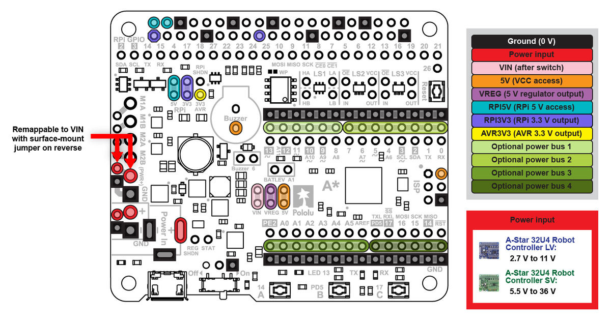
These diagrams identify the I/O and power pins on the A-Star 32U4 Robot Controller with Raspberry Pi Bridge (LV and SV versions); they are also available (along with the power distribution diagram below) as a printable PDF (8MB pdf). For more information about the ATmega32U4 microcontroller and its peripherals, see Atmel’s ATmega32U4 documentation.
 |
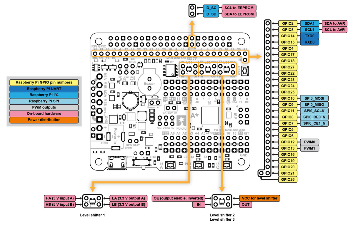 |
Printed on the A* circuit board are indicators that you can use to quickly identify each AVR I/O pin’s capabilities: an analog pin number (prefixed by the letter A) means the pin can be used as an analog input, and a square wave symbol next to the hole pair means the pin can be used as a PWM output. Pin numbers printed as inverted text surrounded by a white box indicate that the pin is used by on-board hardware (see Section 3.10 for more information about pin assignments).
Additional rows of power and ground pins run along the I/O pins to allow easy connections for devices like sensors and servos. The outermost row of pins is connnected to ground, and the middle row is intended for power connections, but not connected by default. The power pins are split into four buses: two buses along the top, split between digital pins 7 and 8, and two buses along the bottom, split between AREF and PD5. You can configure each bus separately by using a jumper to connect it to a voltage source of your choice. (Access points for various supply voltages are available nearby.)
 |


Home | Forum | Blog | Support | Ordering Information | Lists | Distributors | BIG Order Form | About | Contact
© 2001–2026 Pololu Corporation
