Support » Pololu A-Star 32U4 Robot Controller User’s Guide » 3. A-Star 32U4 Robot Controller with Raspberry Pi Bridge »
3.2. User interface
 |
LEDs
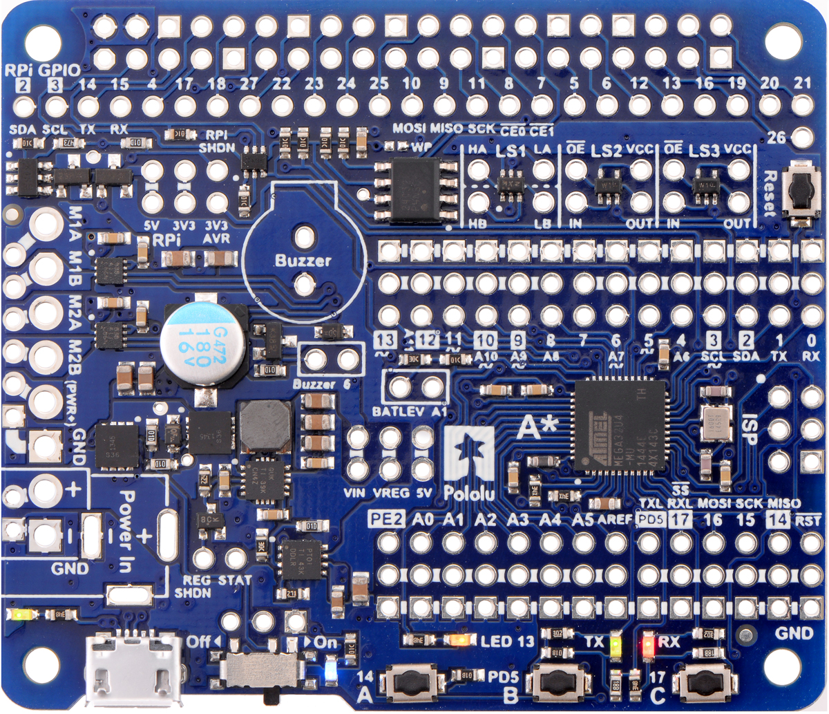
The A-Star 32U4 Robot Controller has five indicator LEDs.
- A yellow user LED is connected to Arduino digital pin 13, or PC7. You can drive this pin high in a user program to turn this LED on. The A-Star 32U4 Bootloader fades this LED on and off while it is waiting for a sketch to be loaded.
- A green user LED is connected to PD5 and lights when the pin is driven low. While the board is running the A-Star 32U4 Bootloader or a program compiled in the Arduino environment, it will flash this LED when it is transmitting data via the USB connection.
- A red user LED is connected to Arduino pin 17, or PB0, and lights when the pin is driven low. While the board is running the A-Star 32U4 Bootloader or a program compiled in the Arduino environment, it will flash this LED when it is receiving data via the USB connection.
The AStar32U4 library contains functions that make it easier to control the three user LEDs. The green and red user LEDs also share I/O lines with pushbuttons (see below).
- A blue power LED next to the power switch indicates when the controller is receiving power from an external power source connected to the Power In terminals (the power switch must be turned on).
- A green power LED on the left edge of the board near the USB connector indicates when the USB bus voltage (VBUS) is present.
Pushbuttons
The A-Star 32U4 Robot Controller has four pushbuttons: a reset button on the right edge and three user pushbuttons located along the bottom edge of the main board. The user pushbuttons, labeled A, B, and C, are on Arduino pin 14 (PB3), PD5, and Arduino pin 17 (PB0), respectively. Pressing one of these buttons pulls the associated I/O pin to ground through a resistor.
The three buttons’ I/O lines are also used for other purposes: pin 14 is MISO on the SPI interface, and PD5 and pin 17 control the green and red user LEDs. Although these uses require the pins to be driven by the AVR (or SPI slave devices in the case of MISO), resistors in the button circuits ensure that the A* will not be damaged even if the corresponding buttons are pressed at the same time, nor will SPI communications be disrupted. The functions in the AStar32U4 library take care of configuring the pins, reading and debouncing the buttons, and restoring the pins to their original states.
Buzzer
The assembled version of the A-Star 32U4 Robot Controller features a buzzer that can be used to generate simple sounds and music. The buzzer is not present on the SMT-only version, but the buzzer driver circuit is still populated, allowing you to solder in your own buzzer or speaker.
A through-hole jumper next to the buzzer provides a way to connect the buzzer input, labeled Buzzer, to digital pin 6 (which also serves as OC4D, a hardware PWM output from the AVR’s 10-bit Timer4). If you alternate between driving the buzzer pin high and low at a given frequency, the buzzer will produce sound at that frequency. You can play notes and music with the buzzer using functions in the AStar32U4 library.


Home | Forum | Blog | Support | Ordering Information | Lists | Distributors | BIG Order Form | About | Contact
© 2001–2026 Pololu Corporation
