Support » Pololu m3pi User’s Guide » 1. Overview »
1.b. Included Components
The m3pi is available fully assembled with a 3pi robot base or as an expansion kit for the 3pi robot.
 |
Fully-assembled Pololu m3pi robot. |
|---|
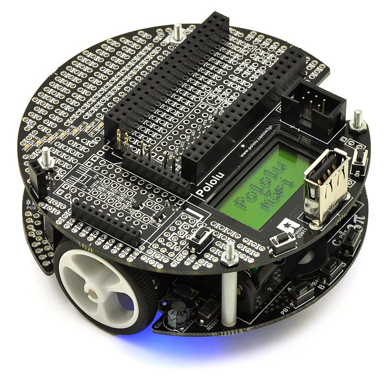
Fully-Assembled m3pi Robot with mbed Socket
The following connectors and components are already installed on the fully-assembled m3pi robot (as shown in the picture on the right):
- mbed socket
- XBee socket
- USB A connector
- 2-pin battery-charging header
- Power pushbutton
- Two general-purpose pushbuttons
- 6-pin shrouded ISP connector
- All of the pins needed to connect to the 3pi robot base (male headers on the expansion PCB and matching female headers on the 3pi base)
 |
Hardware included with the Pololu m3pi robot. |
|---|
The fully-assembled m3pi robot also includes some optional hardware and connectors:
- One 1×11 0.1″ female header and one 1×12″ female header for adding a Wixel socket to the m3pi
- Three red shorting blocks, three yellow shorting blocks, and three black shorting blocks (the 3pi base ships with three blue shorting blocks already in place)
- Two red LEDs and two green LEDs
- One 12″, 6-pin ISP cable
m3pi Expansion Kit for 3pi Robot
 |
Pololu m3pi expansion kit. |
|---|
The m3pi expansion kit PCB has all of the surface-mount components populated, but none of the through-hole components ship soldered in. When combined with a 3pi robot (not included), the m3pi expansion kit includes everything required to make your own fully-assembled m3pi robot as pictured in the section above. These components are shown in the picture on the right and include:
- Two 2×20 0.1″ female headers for adding an mbed socket
- One 1×11 0.1″ female header and one 1×12″ female header for adding a Wixel socket
- Two 1×10 2mm female headers for adding an XBee socket
- One extended 2×7 0.1″ male header and two extended 1×2 0.1″ male headers for connecting the expansion PCB to a 3pi base
- One 2×7 0.1″ female header and one 1×2 0.1″ female header for soldering to the 3pi base so it can accept the male connectors of the m3pi expansion PCB
- One 1×2 0.1″ female header for use as a charge port on the expansion PCB
- Three 1×2 0.1″ male headers for use with shorting blocks for optional configuration of m3pi PCB connections (three blue shorting blocks are also included)
- One 6-pin shrouded ISP connector that can be used with the included 12″, 6-pin ISP cable to optionally let the mbed program the 3pi base
- One USB A connector (can be used when the mbed is acting as a USB host)
- Three pushbuttons for use as a power button and two general-purpose buttons on the expansion PCB
- Four screws, spacers, and nuts for mounting the expansion PCB to the 3pi base


Home | Forum | Blog | Support | Ordering Information | Lists | Distributors | BIG Order Form | About | Contact
© 2001–2026 Pololu Corporation
