Support » Pololu USB AVR Programmer User’s Guide » 3. Getting Started in Windows »
3.c. Programming AVRs Using AVR Studio 4
This tutorial covers the older AVR Studio 4, which is no longer supported by Atmel. For a tutorial on the newer Atmel Studio see Section 3.b. For a tutorial on AVR Studio 4 for Orangutan and 3pi robot users, see the Programming Orangutans and the 3pi Robot from AVR Studio 4 guide.
The following tutorial covers the steps needed to program AVRs in Windows using AVR Studio 4 and a Pololu USB AVR programmer. Specifically, we will write a simple program to blink an LED connected to pin PD1 of an AVR. If you want to program an AVR that does not have an LED connected to pin PD1, the code in this tutorial may need to be modified.
You will need to download and install several pieces of software:
- The Pololu USB AVR Programmer’s drivers (see Section 3.a).
- WinAVR: WinAVR is a free, open-source suite of development tools for the AVR family of microcontrollers, including the GNU C/C++ compiler for AVRs (avr-gcc).
- AVR Studio 4: AVR Studio 4 is a free integrated development environment (IDE) for programming AVRs offered by Atmel. AVR Studio 4 works with the WinAVR avr-gcc compiler and contains built-in support for AVR ISP programming.
If you have an Orangutan or 3pi and want to jump straight in to using your USB AVR programmer, you can skip steps 1–3 by downloading the AVR Studio project these steps would create. Determine the microcontroller on your device, download the corresponding file below, extract all the files to a directory, open the AVR Studio project file (BlinkLED.aps), and proceed to step 4.
- mega48: BlinkLED_m48.zip (9k zip)
- mega168: BlinkLED_m168.zip (9k zip)
- mega328: BlinkLED_m328.zip (9k zip)
Open AVR Studio and click New Project. Select AVR GCC for the project type. Enter the project name and initial file name. In the screenshot below, we named our project “BlinkLED” and elected to have a folder called “C:\BlinkLED” created containing the blank file “BlinkLED.c”. Click Next >>. DO NOT click “Finish” yet. If you do accidentally click “Finish”, you will not be able to perform step 2 and will instead have to set the device by going to the “Project” menu and selecting “Configuration Options”.
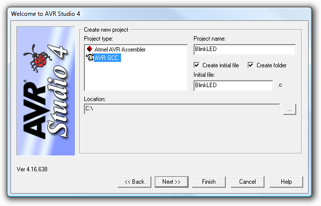
Creating a new AVR Studio 4 project, step 1
Select AVR Simulator as the debug platform and then select the appropriate device for your target AVR. For an Orangutan or 3pi Robot, this will either be ATmega48, ATmega168, ATmega328P, ATmega324PA, ATmega644P, or ATmega1284P depending on which chip your Orangutan or 3pi Robot has. Click Finish.
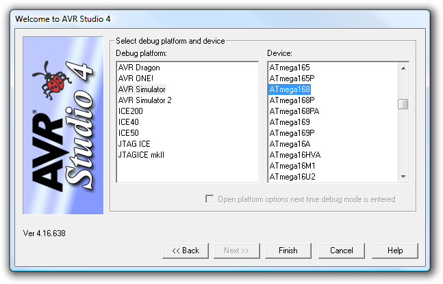
Creating a new AVR Studio 4 project, step 2
Write your program in BlinkLED.c as seen in the screen shot below and click the Build button on the toolbar (or press F7).
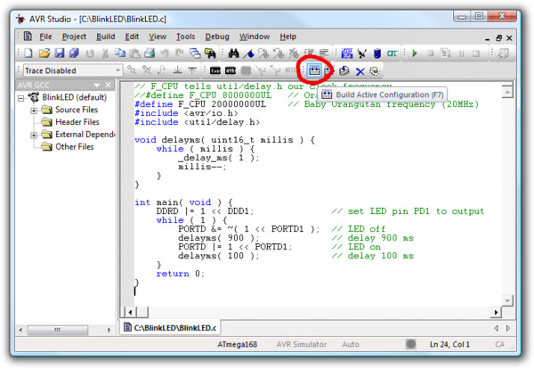
Building a project with AVR Studio
Note: You will probably want to customize this program slightly if the clock frequency of your AVR is not 20 MHz. F_CPU should be defined as the clock frequency of your AVR in units of Hz. If you do not make this change, the timing of delayms() will be off, but the LED will still blink.
Make sure your USB AVR programmer is connected to your computer via its USB A to mini-B cable and then click the Display the ‘Connect’ Dialog button on the toolbar. You can also accomplish this by going to the “Tools” menu and selecting Program AVR > Connect….
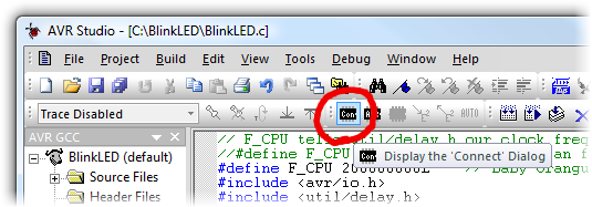
Connecting to the programmer with AVR Studio
This will bring up a programmer selection dialog. Select AVRISP as the platform. The USB AVR programmer uses AVR ISP version 2, which is written as AVRISPv2. Please note that this is not the same as AVR ISP mkII. Select the port name of your programmer if you know what it is, or select Auto and AVR Studio will try all the ports until it detects the programmer. You can determine your programmer’s port name by looking in the “Ports (COM & LPT)” list of your Device Manager for “Pololu USB AVR Programmer Programming Port”. Click “Connect…” to bring up the ISP window.
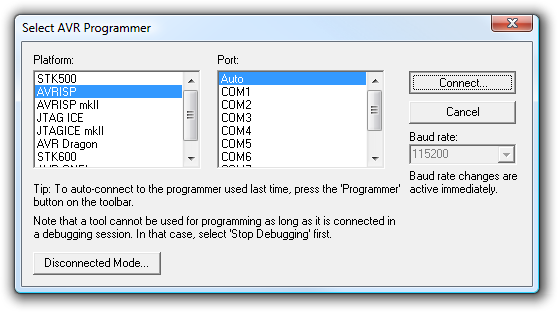
AVR Studio 4’s programmer-selection dialog
If the ISP window does not appear when you click “Connect…”, your computer cannot detect the programmer. Please see Troubleshooting (Section 8) for help identifying and fixing the problem.
If AVR Studio brings up a dialog asking if you want to upgrade (or downgrade) your programmer’s firmware, click Cancel to ignore the message and use your programmer. To prevent this dialog from appearing in the future, use the Configuration Utility (Section 3.e) to change the programmer’s hardware and software version numbers.
Select the Main tab. In the dropdown box that lists AVR models, select the same device that you selected when you created the project. For an Orangutan or 3pi Robot, this will either be ATmega48, ATmega168, or ATmega328P.
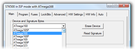
Selecting the device for ISP programming in AVR Studio
If you have not done so already, connect the programmer to the target device using the 6-pin ISP cable. Make sure the cable is oriented so that pin 1 on the connector lines up with pin 1 on your target device! You can test the connection by going to the Main tab and clicking the Read Signature button. This sends a command to the target AVR asking for its device signature. If everything works correctly, you should see “Signature matches selected device”. If the signature does not match the selected device, you probably have the wrong device selected (or possibly your target device is turned off). If reading the signature fails entirely, please see Troubleshooting (Section 8) for help getting your connection working.
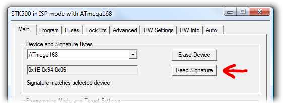
Reading the device signature in AVR Studio’s Main ISP tab
Now it is time to program your target device. Select the Program tab. Your Input HEX File in the Flash section needs to be the hex file that was generated when you built your program. You can browse for this using the "..." button to the right of the input file text box. If you navigate to your project’s folder, you should find it as “default\<project name>.hex”. Click the Program button (make sure you click the one in the Flash section, not one in the “EEPROM” or “ELF Production File Format” sections!).
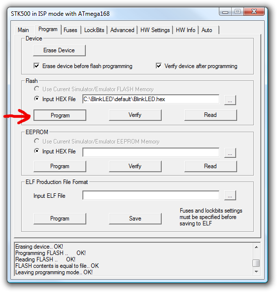
AVR Studio’s Program ISP tab
As your USB AVR programmer programs the AVR, you should see all three LEDs flicker and you should see the following text appear at the bottom of the window:
Reading FLASH input file.. OK
Setting mode and device parameters.. OK!
Entering programming mode.. OK!
Erasing device.. OK!
Programming FLASH ..      OK!
Reading FLASH ..      OK!
FLASH contents is equal to file.. OK
Leaving programming mode.. OK!
If there were no problems, the LED connected to PD1 of your AVR should now be flashing! Note that if you are trying this on a 3pi robot and you have not yet soldered in the optional through-hole LEDs, the flashing LED will be on the bottom of the robot. If there was a problem, please see Troubleshooting (Section 8) for help identifying and fixing it.


Home | Forum | Blog | Support | Ordering Information | Lists | Distributors | BIG Order Form | About | Contact
© 2001–2025 Pololu Corporation
