Support » Pololu USB AVR Programmer User’s Guide » 3. Getting Started in Windows »
3.b. Programming AVRs using Atmel Studio
- 3.b.1. Adding Devices to Atmel Studio 6
- 3.b.2. Using Advanced Features of Atmel Studio
- 3.b.3. Faster programming with F5 in Atmel Studio
If you have an Orangutan or 3pi Robot or wish to use the Pololu AVR C/C++ Library for some other reason, we recommend following the Pololu AVR Programming Quick Start Guide instead of this tutorial.
The following tutorial covers the steps needed to program AVRs in Windows using Atmel Studio and a Pololu USB AVR Programmer. Atmel Studio is a free integrated development environment (IDE) provided by Atmel. In this tutorial, we will write a simple program to blink an LED connected to pin PD1 of an AVR. If you want to program an AVR that does not have an LED connected to pin PD1, the code in this tutorial can be modified.
You will need to:
- Download and install Atmel Studio by following the instructions on Atmel’s website. If you use Windows Vista, you should download Atmel Studio 6.2, because that is latest version that supports Windows Vista. This tutorial was written for Atmel Studio 7.0 and Atmel Studio 6.2.
- Install the Pololu USB AVR Programmer’s drivers on your computer. See Section 3.a for instructions.
- Upgrade your programmer’s firmware to version 1.07 or later if necessary. See Section 9 for instructions. If your programmer was shipped from Pololu after 2012-02-29, then you already have the right firmware.
- If you are using Atmel Studio 6 or older, you might need to add an XML file to Atmel Studio to make it support the AVR you wish to program. See Section 3.b.1 for instructions.
After you have completed these prerequisites, you can create a new Atmel Studio project:
- Open Atmel Studio and click New Project. In the New Project dialog, select GCC C Executable Project for the template. Enter the project name and location. In this tutorial, we will name our project “BlinkLED” and put it in the “C:\” directory, but you can choose a different name and location if you would like. Uncheck the Create directory for solution box to simplify the directory structure of your project. Click OK.
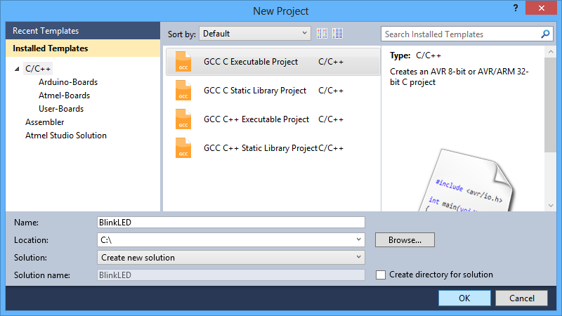 |
The New Project dialog of Atmel Studio 6. |
|---|
- In the Device Selection window, select the device name of your specific AVR. Click OK to create the project.
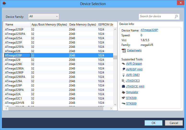 |
The Device Selection dialog of Atmel Studio 6. |
|---|
- Remove the template code that was automatically placed in BlinkLED.c and replace it with the code below:
#define F_CPU 20000000    // AVR clock frequency in Hz, used by util/delay.h
#include <avr/io.h>
#include <util/delay.h>

int main() {
	DDRD |= (1<<DDD1);          // set LED pin PD1 to output
	while (1) {
		PORTD |= (1<<PORTD1);   // drive PD1 high
		_delay_ms(100);         // delay 100 ms
		PORTD &= ~(1<<PORTD1);  // drive PD1 low
		_delay_ms(900);         // delay 900 ms
	}
}
Note: The value of F_CPU should be the clock frequency of your AVR in units of Hz, so if your AVR is not running at 20 MHz you will need to change that line. If you do not make this change, the timing of _delay_ms() will be off, but the LED will still blink.
- Click the Build Solution button on the toolbar (or press F7) to compile the code.
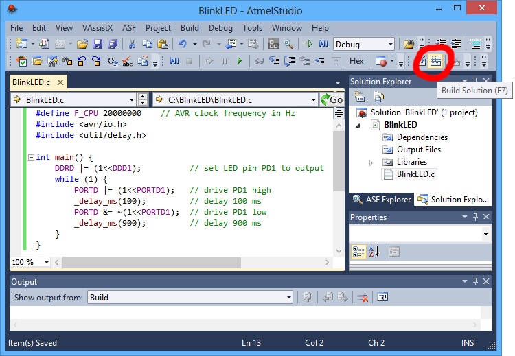 |
Building a project with Atmel Studio 6. |
|---|
- Make sure your USB AVR programmer is connected to your computer via its USB A to mini-B cable and then select Add target… from the Tools menu. Select STK500 as the tool. Select the COM port that has been assigned to the programmer’s programming port, and click Apply. If you are not sure which COM port to select, look in the Device Manager under the “Ports (COM & LPT)” list. This step can be skipped if you have done it before.
 |
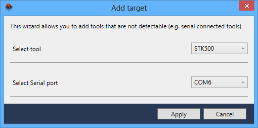 |
The “Add target” dialog box in Atmel Studio 6. |
|---|
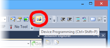
- Click the Device Programming button on the toolbar. You can also select Device Programming from the Tools menu.
 |
- This will bring up the Device Programming dialog. For the Tool, select the STK500 that you added earlier. Select the same device you selected earlier. If your device is not in the list, you might need to add it to the list by following the instructions in Section 3.b.1. For the Interface, select ISP. Click Apply.
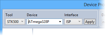 |
Selecting a programmer, device, and interface in the Device Programming dialog of Atmel Studio 6. |
|---|
If you got an error that says “Unable to connect to tool STK500” and you see an error message in the Output pane in the main window that says “The signature of the attached tool is AVRISP_2, which is unexpected.” then you need to upgrade your programmer’s firmware to version 1.07 or later (see Section 9). If you get a different error, see Troubleshooting (Section 8) for help identifying and fixing the problem.
- If you have not done so already, connect the programmer to the target device using the 6-pin ISP cable. Make sure the cable is oriented so that pin 1 on the connector lines up with pin 1 on your target device, and that the target device is powered on. You can test the connection by clicking the Read button next to the Device Signature box. This sends a command to the target AVR asking for its signature. If everything works correctly, you should see a number in hex notation appear in the Device Signature box. If you get an error about the signature being wrong, you might have selected the wrong device. If you get a warning that says “Read voltage … is outside selected device’s operating range” then double check to make sure that your device is powered and that you have upgraded the programmer to firmware version 1.07 or later. For more help getting your connection working, see Troubleshooting (Section 8).
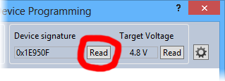 |
Reading the device signature of an AVR in Atmel Studio 6. |
|---|
- Now it is time to program your target device. Select the Memories section on the left. The Flash box should contain the path to the ELF file that was generated when you built your program. If it does not, you can browse for this using the “…” button to the right of the text box. If you navigate to your project’s folder, you should find it as “Debug\<project name>.elf”. Click the Program button in the Flash box.
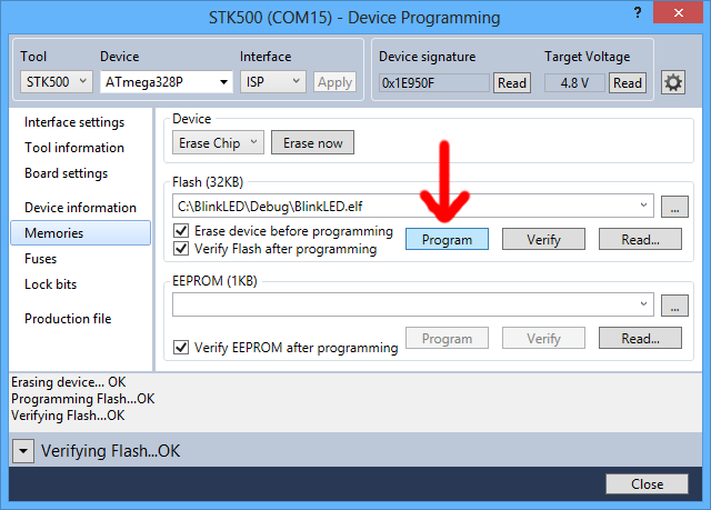 |
The Memories section of the Device Programming dialog in Atmel Studio 6. |
|---|
As your USB AVR Programmer programs the AVR, you should see all three LEDs flicker and you should see the following text appear at the bottom of the window:
Erasing device... OK
Programming Flash...OK
Verifying Flash...OK
If there were no problems, the LED connected to PD1 of your AVR should now be flashing! Note that if you are trying this on a 3pi robot and you have not yet soldered in the optional through-hole LEDs, the flashing LED will be on the bottom of the robot. If there was a problem, please see Troubleshooting (Section 8) for help identifying and fixing it.


Home | Forum | Blog | Support | Ordering Information | Lists | Distributors | BIG Order Form | About | Contact
© 2001–2026 Pololu Corporation
