Support » Building Line Following and Line Maze Courses »
4. Building the Line Maze Course
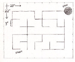 |
A sketch of the maze course. |
|---|
Step 1: Plan your maze.
The maze we will be building in this section is aligned on a 3" grid, so that parallel segments are never closer than 3". This grid is quite small, but it fits the 3pi robot well, and it allows an interesting maze to fit on a single sheet of posterboard. If you want to use a larger grid, you can combine multiple sheets together, just like we did with the line course. You can also use multiple sheets to make more complicated courses, and the sheets can even be rearranged to make a variety of different mazes. At Pololu, our favorite maze is an 8’×8’ course, using a 6" grid, made out of four 4’-square pieces of whiteboard material that can be rearranged to form many different combinations.
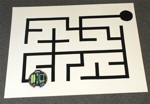
The course drawn at right has an important feature: it has no loops. This means that your robot can navigate through the entire course, starting from any point, by following a very simple “left hand on the wall” strategy, where it turns left, if possible, at every intersection. Looped mazes are more complicated, because this simple strategy will often cause the robot to get stuck in an infinite loop or to bypass an important section of the maze. For a robot to navigate a looped maze, it needs to be able to measure its current position accurately enough to determine when it has encountered a loop. This requires precision timing or some kind of wheel encoding, and it adds another level of complexity to the program. We recommend using no loops for your first maze.
For our course, we’ve also been careful to make the total length of the side-paths equal on the right and left sides of the shortest path through the maze. This means that a “left hand” and a “right hand” robot should take about the same amount of time to solve the maze.
Step 2: Pencil the course onto the posterboard sheet.
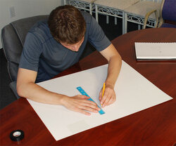 |
Draw the grid lightly in pencil. |
|---|
Start by marking the edges of the posterboard with 3" tick marks, then using a long straightedge (such as another piece of posterboard) to lightly pencil in the grid. Then, with darker lines, highlight the segments that will become part of the maze.
Step 3: Place electrical tape along each segment of the maze.
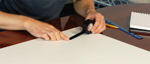 |
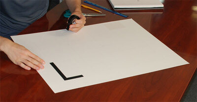
Start with a cleanly-cut piece of tape for the first segment. |
|---|
Each line segment of the maze should be made with a cleanly-cut piece of electrical tape that stretches 3/8" past the grid point on either side, so that it will be aligned with the segments at right angles to it.
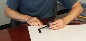 |
Make the next segment with a separate piece of tape. |
|---|
Make each piece as long as possible, overlapping them at the corners and intersections. You’ll need to pay careful attention to the corners so that they come out as clean as possible. Any extra pieces of tape that stick out at incorrect angles could cause a robot to confuse, for example, corners with T-intersections. When debugging your code, you don’t want to worry about whether the robot was confused by the course or just badly programmed, so make it neat!
 |
Cut the end of each segment as straight as possible. |
|---|
Cuts should be made at precise right angles. Don’t worry if you cut the tape too short; if you can’t stretch it to fit, you can carefully peel it off and try again with a new piece.
Here’s what the first corner of our maze looks like:
 |
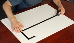 |
This long segment is made with a single piece of tape. |
|---|
We put a long straight segment in the middle of the maze. After learning the path, an advanced robot could take advantage of this, accelerating briefly to full speed, to finish the maze a fraction of a second faster than a robot with a simpler program. This will give you and your competitors a reason to keep improving your code!
Note that two pieces of tape can overlap to form a four-way crossing, without any ugly cuts at the intersection:
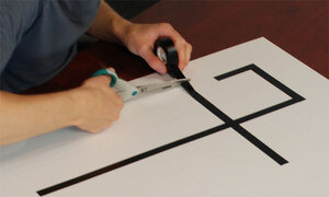 |
This intersection is made with another piece, overlapping the previous one. |
|---|
Keep putting down segments of tape until you have completely copied your design.
 |
Putting down the last line segment of the course. |
|---|
 |
The dot at the finish requires extra care. |
|---|
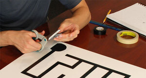
We use a 3" circle to signify the end of the maze. Since it is so different from the straight lines and corners in the rest of the course, the circle can actually be very difficult to detect. You’ll spend a significant amount of time making your program detect the ending reliably, so make sure that you also spend enough time to make the circle look nice. You could also use a 3" square block to make a simpler ending, but make sure that it doesn’t get too close to the nearby lines.
 |
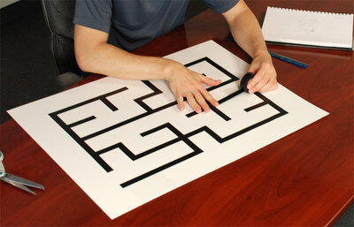
A 3pi ready to run on the finished course. |
|---|
Your maze is now complete! It’s perfect for the 3pi robot or your own custom robot based on a QTR sensor array. For more information on how to actually program a maze-solving robot, please take a look at Section 8 of the 3pi user’s guide. You might also want to take a look at this maze-solving algorithm presentation (505k pdf) written by customer (and robotics professor) R. Vannoy.
Related products


Home | Forum | Blog | Support | Ordering Information | Lists | Distributors | BIG Order Form | About | Contact
© 2001–2026 Pololu Corporation
