Support » Application Note: Using the Motor Driver on the 3pi Robot and Orangutan Robot Controllers »
6. Motor Voltage Waveforms
The following oscilloscope screen captures demonstrate how our motor control functions from Section 5 affect the motor driver outputs. These captures were taken using an Orangutan LV-168 running off of three AA batteries with a free-running motor connected. At 6 V, the motor has an approximate free-run current of 400 mA and stall current of 7 A. A single 0.1 μF capacitor is soldered between the motor terminals for noise suppression.
M1_forward(191);
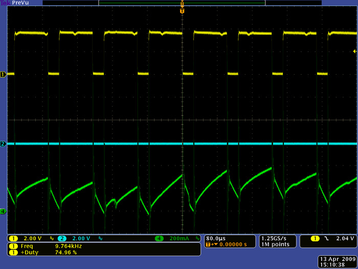 |
Motor outputs M1A (blue) and M1B (yellow) for driving “forward” at 75% duty cycle (OCR0B=191, OCR0A=0). The green channel shows motor current. |
|---|
If you use the Pololu AVR library, the equivalent function call would be set_m1_speed(191) (see the Pololu AVR command reference for more information).
You can see that the M1B output is high 75% of the time and low 25% of the time, and the M1A output is low 100% of the time. While M1B is high, the motor is being driven forward, and while M1B is low, the motor is braking. The net effect is that the motor speed is approximately 75% of its full speed at the supplied motor voltage.
The green line shows the current flowing through the motor. During the high period of M1B’s duty cycle, the current ramps up as the motor draws current from the driver, and during the low period of the duty cycle the current drops as the motor brakes. The motor used for this test is particularly noisy at high speeds (note that the current draw is not always the same from one PWM cycle to the next).
M1_reverse(63);
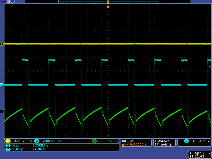 |
Motor outputs M1A (blue) and M1B (yellow) for driving “reverse” at 25% duty cycle (OCR0B=63, OCR0A=0). The green channel shows motor current. |
|---|
If you use the Pololu AVR library, the equivalent function call would be set_m1_speed(-63). (see the Pololu AVR command reference for more information).
Here the M1A output is high for 25% of the time and low for 75% of the time, and the M1B output is low 100% of the time. While M1A is high, the motor is being driven in reverse, and while M1A is low, the motor is braking. The net effect is that the motor speed is approximately 25% of its full speed at the supplied motor voltage.
The green line shows the current flowing through the motor. Note that the zero point of this has been moved up since the current is flowing in the opposite direction when the motor is moving in reverse. At lower speeds, the motor noise decreases and the current draw does not change much from one PWM cycle to the next.


Home | Forum | Blog | Support | Ordering Information | Lists | Distributors | BIG Order Form | About | Contact
© 2001–2026 Pololu Corporation
