Pololu Blog »
New products: DRV8256E/P motor driver carriers
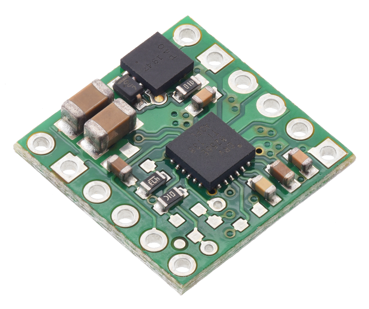 |
We’re pleased to announce our inaugural products based on the DRV8256E and DRV8256P motor drivers from Texas Instruments, which we are especially excited about. These little carrier boards can deliver a continuous 1.9 A to a single brushed DC motor at voltages from 4.5 V to 48 V, so they have some of the broadest operating ranges of any of our drivers, and they can handle short bursts of considerably higher current (up to 6.4 A for less than a second). They also feature configurable active current limiting, which can help make them good choices for a motor that might only draw around an amp when running but much more when starting.
|
|
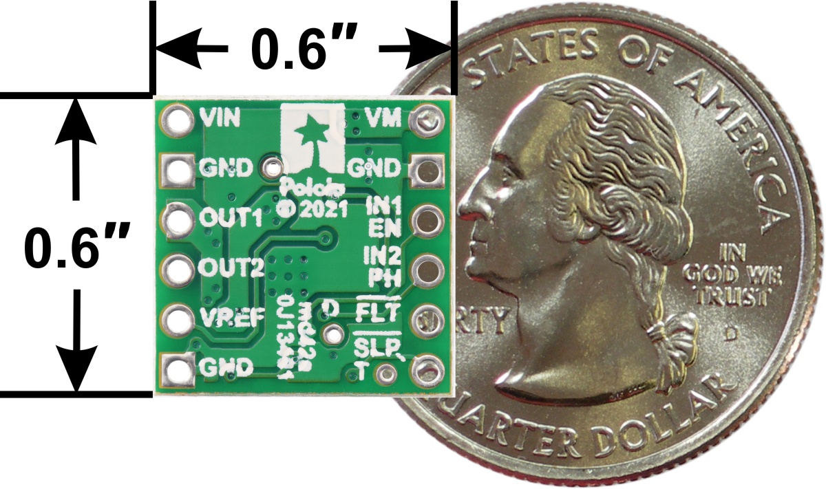
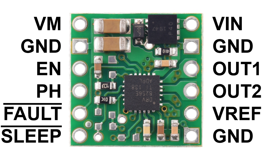
The DRV8256E and DRV8256P are very similar, and we use the same printed circuit board for both chips, but their control interfaces are different. The E version provides a phase/enable interface that lets you control a motor with a single PWM speed signal along with a simple digital direction signal, while the P version provides an IN/IN interface that gives you direct control over the motor outputs but requires two PWM signals for bidirectional speed control.
However, there is also a tradeoff with these two ICs. The DRV8256P uses drive/brake operation, shorting the motor outputs together and electrically braking the motor during the off portion. Many other TI drivers with phase/enable interfaces (like the DRV8838) also use drive/brake, but the DRV8256E does not: it operates in drive/coast mode, where the motor outputs are high impedance during the off portion of the PWM cycle, allowing the motors to coast. We don’t know why TI made a different decision for the DRV8256E, but it seems likely they have some high-volume customers who prefer it this way.
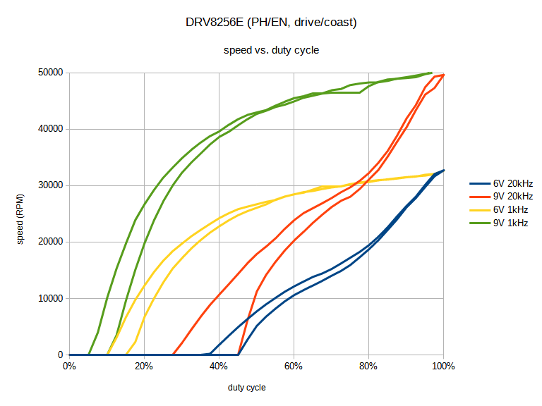
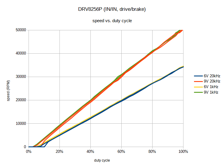
In our experience, drive/brake mode provides a much more linear relationship between PWM duty cycle and motor speed, so for an application where that is important, you might choose to accept the need for an additional PWM signal to get that improved linearity. These graphs show the difference in one specific scenario (powering a high-power micro metal gearmotor with no load):
|
|
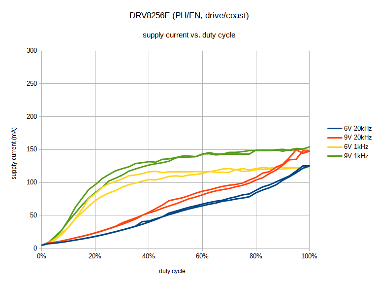
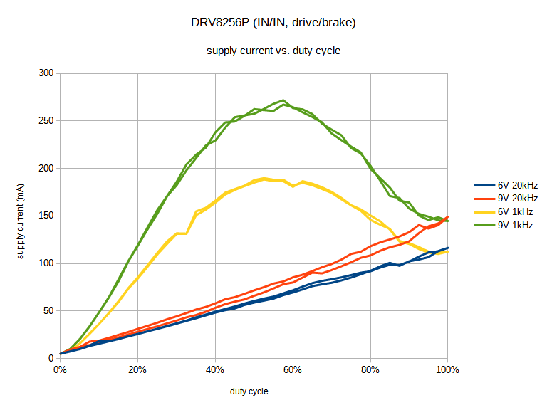
However, graphing the relationship between duty cycle and the current drawn by the motor driver from the supply reveals some more interesting differences. Specifically, at lower PWM frequencies, drive/brake operation uses much more current at intermediate duty cycles as the motor current ramps up and down for each PWM cycle:
|
|
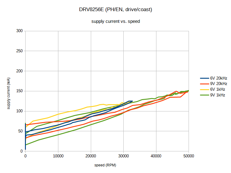
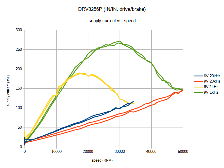
Finally, graphing current draw against motor speed shows that drive/coast can be more efficient for a given speed compared to drive/brake. So for an application with closed-loop speed control where it’s not as important for duty cycle to correspond linearly with speed, using drive/coast might be preferable if the PWM frequency is low.
|
|
If you have any thoughts about drive/brake vs. drive/coast and their use in different applications, we would be interested in hearing about it.
For more information about these drivers, see their product pages:
Related products


-

Polo-BOO! Halloween Sale going on now!
- 30 September 2021Our Polo-BOO! Halloween Sale is back! Get 10% off active Pololu-brand products using coupon code PoloBOO2021 (limit 10 per item) from now until...
-
November 2021 operations update: supply chain disruptions, price increases, and component rationing
- 12 November 2021Nearly two years of operations under the COVID-19 pandemic are behind us. Like many other businesses around the world, our biggest challenges have...
6 comments


We do not recommend paralleling the outputs of two of our DRV8256E carriers. The datasheet for the chip does not mention any special considerations for it, so there is no guarantee the timing of the two drivers will line up well enough to prevent shoot-through or other issues. Depending on your application, one of our larger drivers like the TB67H420FTG or VNH5019 might be more appropriate.
-Claire

That is how the driver is intended to be used. If you still think there is a problem with that, can you elaborate?
Brandon
Table 7.2 in the DRV8256E datasheet is consistent with our documentation. When EN is high, the outputs are driving, and when it is low, they are high impedance (i.e. coasting). Connecting a PWM signal to this pin results in variable speeds proportional to the duty cycle, with the direction of the current controlled by the PH pin (i.e. sign-magnitude operation). We do not explicitly mention it in our documentation, but you can connect a suitably high-frequency PWM signal to the PH pin instead if you want locked-antiphase operation. Is that how you are using yours?
Brandon

Thanks for the elaboration. Why so much negativity? (If you thought you wrote something worthwhile, why would you preemptively say you'll delete your post?) Have we done something besides posting technical information that you think is incorrect?
A lot of your ire seems directed at the alleged nonsense of "disabling the whole chip, at PWM frequencies", which is not what we are suggesting. You can see on page 7 of the datasheet under Recommended Operating Conditions that the EN input is one of the inputs intended to have PWM applied.
And you have heard of sign-magnitude control, right? I am not sure why you are calling it "the Pololu way" when it's a common approach that has a well-established name. While TI's datasheet does not specifically recommend one pin over another for PWM, other similar chips, such as MAX14870, literally call their pins "PWM" and "DIR", with the PWM pin corresponding to the TI "EN" pin on this chip in terms of functionality. And the DRV8256 E and P versions remain anomalous relative to TI's other motor drivers that have similar pairs of versions.
- Jan

Post a comment


Home | Forum | Blog | Support | Ordering Information | Lists | Distributors | BIG Order Form | About | Contact
© 2001–2026 Pololu Corporation
