Pololu Blog »
New product: USB 2.0 Type-C Connector Breakout Board
 |
We have just released our USB 2.0 Type-C Connector Breakout Board. The Type-C connector has become increasingly common on devices like smartphones and notebook computers over the past few years, and it offers a number of interesting improvements over the legacy USB A and B connectors it is supposed to replace.
One of the most noticeable features is that the connector is reversible: you can plug a Type-C cable into a receptacle with either side up, and since Type-C ports can be used for both USB hosts and USB devices, the two ends of the cable can be interchangeable too. The USB-C specification also provides for negotiation of increased power (up to 20 V and 5 A) and alternate uses of the USB interface wires.
 |
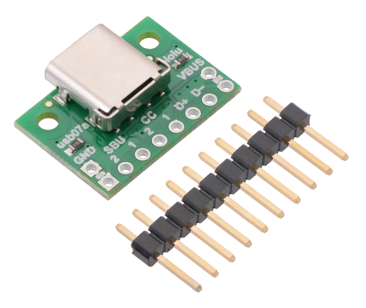
All of this flexibility comes at a cost. The Type-C connector itself, which measures about 1 cm (0.4″) square, has 24 separate tightly-packed pins:
- 4 power pins (VBUS)
- 4 ground pins
- 4 USB 2.0 data pins (D+ and D−, each duplicated for reversibility)
- 8 USB 3.1 SuperSpeed data pins
- 2 configuration pins
- 2 auxiliary (sideband) pins
Making all the required connections for a prototype or hobby project is therefore a much more daunting task with a USB-C receptacle compared to a Type-A or Type-B connector with only 4 or 5 pins. This is where our Type-C connector breakout board comes in, exposing all the pins necessary for USB 2.0 communication along a row of 0.1″-spaced holes. (Note that the board does not break out the USB 3.1 SuperSpeed differential pairs.)
If you are designing something that uses USB-C, you also need to consider what to do with the Configuration Channel (CC) pins. These pins are used to determine the role of a port when it is connected—whether it is a USB host or device, and whether it provides or consumes power—and they are also used to configure more advanced functionality like higher-voltage power delivery and alternate modes that allow other protocols over the USB interface.
Since we expect many users of this breakout board to employ it as a USB device port, we populate the board with pull-down resistors on the CC pins that make it a straightforward replacement for a Type-B, Mini-B, or Micro-B port. If you have a different application in mind, you might want to disconnect or remove the resistors yourself, or you can contact us about customizing the termination resistors.
We are interested in hearing any feedback you might have about the USB Type-C connector in general, this board in particular, and any follow-on boards you would like to see. Are you excited about using Type-C connectors instead of Micro-B? Would you have a use for the USB 3.1 SuperSpeed pins brought out to 0.1″-spaced holes? Do you want something with an on-board configuration controller that makes it easier to set up USB Power Delivery or other advanced functionality? Please share your thoughts in the comments below.
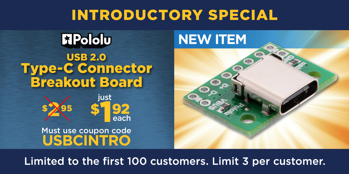
As with all our new products this year, we are offering a special introductory promotion. You can get up to three of the new breakout boards for just $1.92 each, limited to the first 100 customers using coupon code USBCINTRO.
Related products

-
New products: U3V70x high-current boost voltage regulators
- 16 August 2018Today we are finally releasing our new U3V70x family of boost regulators, which are now our highest-current boost regulators. (I said “finally”...
-
New products: more new QTR HD sensor arrays by student engineering interns
- 23 August 2018All the student engineering interns we had over the summer from out-of-town colleges are headed back to school, so I get to announce the release of...
18 comments


Here is an answer to a StackExchange question about using USB-C as a power source that you might find helpful. Our board includes 5.1k pulldowns on the two CC pins, so it should act as an upstream-facing port (UFP) by default and provide 5 V on VBUS when connected to a host port or charger (downstream facing port, or DFP).
You should be able to draw current from it without doing anything else with the CC pins, but if you want more than 500 mA and want to be compliant with the USB specification, your device should also measure the voltage on CC to check how much current it is allowed to draw from the DFP, as described in step 5 of the answer I linked.
Kevin

Thank you for this detailed blog post. Yes, this product is really cool and saves the hassle of wiring really small pads.
I have a question on using this break out board with a micro-USB port on an ATMEGA 32U4 feather. Is there a connector cable that connects the pins on here with the feamle receptacle on the Feather?
If so could you give me the details? If not can you help me with the connections coming out of that port? My application is that this port will act as a power sink (connected to computer or charging dock) Thank you very much!

If you are using this strictly for power, you would only need to wire VBUS and GND to the appropriate pins/lines on your 32U4 Feather. The Feather appears to have a pin labeled USB that is a connection point for its USB bus voltage. If you additionally want to pass USB data through the Type-C connector, you would have to connect the D+ and D- lines as well. These would probably have to be connected through the Feather's on-board USB receptacle, since it does not provide alternate places to connect those.
We do not carry an adapter cable like the one you are describing, and I do not have a suggestion on where you would be able to find one. However, you might also consider using a USB Micro-B plug breakout board, such as this one from SparkFun:
https://www.sparkfun.com/products/10031
-Dan
That's helpful. What we are doing is to get a USB micro male to 5 pin mother board cable that will do the same thing as the break out board. Its a cool idea though.
Now, do you have KiCAD or Solidworks (3D) files for this component?
https://www.pololu.com/product/2585/resources
-Dan
We had received the product and performed a connection test with it. Our application is to connect the USB 2.0 port on computer via the Polulu connector to the Micro USB port on Feather BLE 32U4. We did this using a 5 pin adapter cable on Amazon. https://www.amazon.com/gp/product/B01MXMZL49?ref=ppx_pt2_dt_b_prod_image
However though the board was powering on, there seems to have been no signal communication between the Feather and the Arduino program on the computer...
We checked the voltages on the terminals after setting up:
VBUS: 5V
D+: 3.3V
D-:0
GND:0
Is there any thing we can do to run our application?
https://forum.pololu.com/
-Dan
One final question: Do the two GND terminals on the board need to be connected and wired ? Or is connecting one on the bottom row enough?
-Dan

I would like to ask if you have a library file for eagle for this specific USB connector or if you know of a link, as I am staring at a few on my desk, but can't complete a project, as I am not good at making eagle items.
Any help would be greatly appreciated.
Thank you.

We do not use Eagle, so we do not have Eagle files. You can find DXF drill guide and 3D models files under the "Resources" tab of the connectors product page:
https://www.pololu.com/product/2585/resources
-Derrill

I'm not sure what you're asking; USB does not allow devices to be daisy-chained, so you typically need a hub to connect multiple devices to a host. If you have additional questions or would like to discuss this further, please post on our forum, which is more suited for technical discussions.
Kevin

Do I need to edit the board somehow. Different cc values? Or can I just connect 5v ground and d+ d-?
Thanks for the great products you guys do, btw.
It looks like you also posted your question on our forum; I have replied to it there.
Kevin


The usb07a boards use 0603 resistors (imperial units). Can you tell me why you are asking? In case it is helpful, we have a 3D CAD model of the board that shows the resistors on the product page under the
Resourcestab.
- Patrick
Post a comment


Home | Forum | Blog | Support | Ordering Information | Lists | Distributors | BIG Order Form | About | Contact
© 2001–2026 Pololu Corporation
