Pololu Blog »
Creepy eyes Halloween prop upgrade

There are only a couple days left in our Halloween sale! Visit the sale page for more information, and if you are in need of some inspiration, check out our Halloween-tagged blog posts for some sample projects, including this upgrade to my creepy eyes prop:
 |
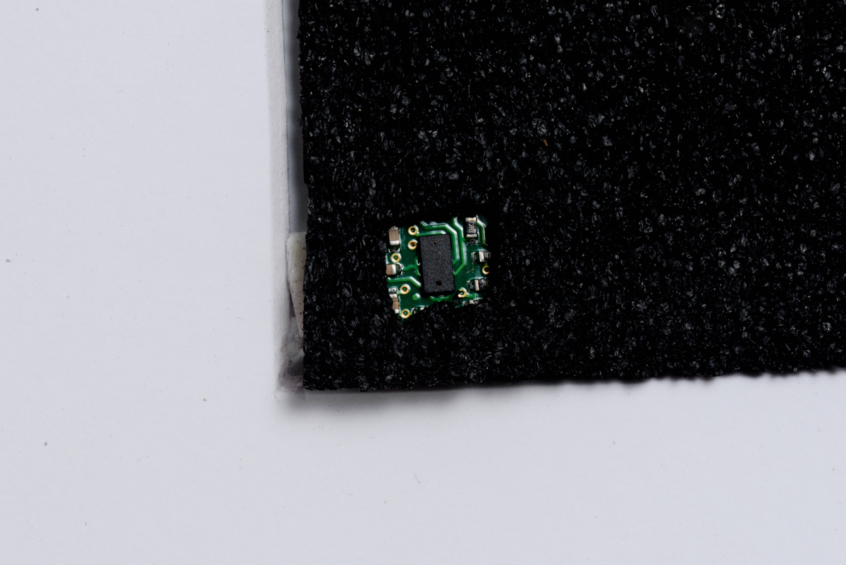
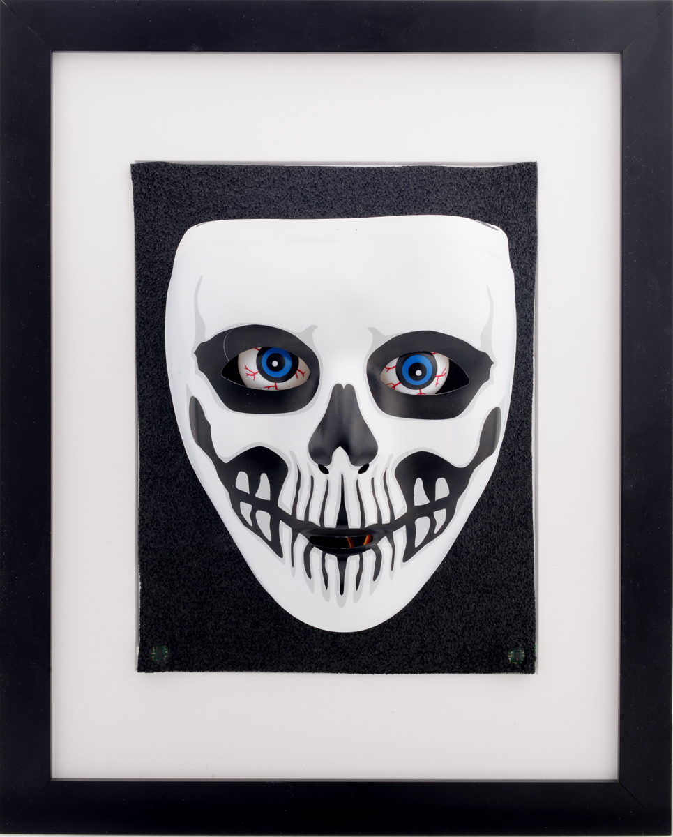
I finally got around to upgrading my creepy eyes Halloween prop. As shown above, I mounted the mask on a picture frame to make it more presentable. I also added some of our VL53L0X time-of-flight distance sensor carriers so that the eyes could follow people in front of the mask. I camouflaged the sensors behind the black layer of foam behind the mask. Below is an image showing how the sensors were hidden in the lower corners of the picture frame:
 |
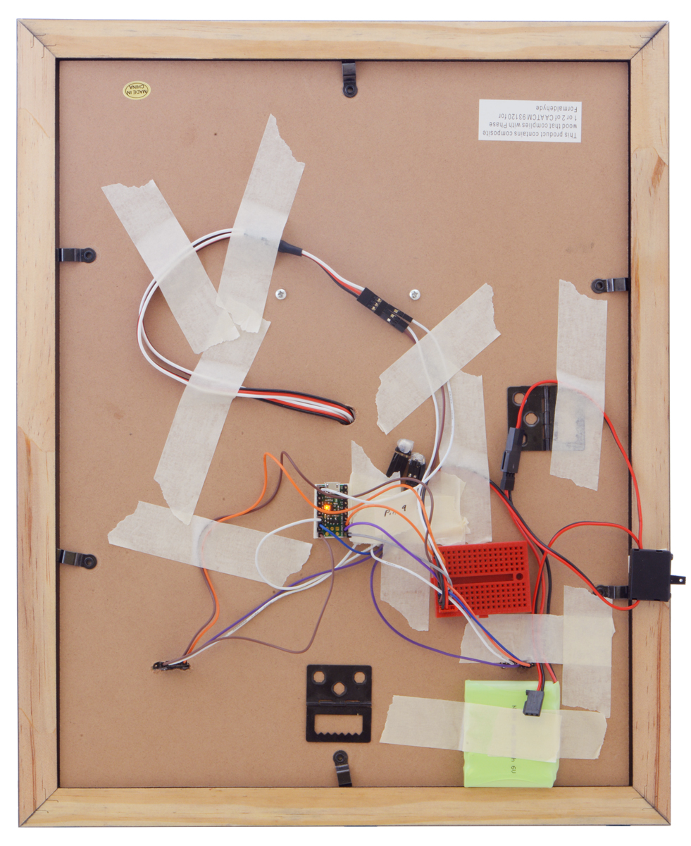
I also swapped the Maestro out for an A-Star 32U4 micro, so I could communicate with the sensors through I²C. Due to switching to the A-star micro, I added one of our small solderless breadboards to help distribute power and a servo Y splitter cable since both sub-micro servos can use the same signal. I also added a power switch and used some of our premium jumper wires to make connections. You can see all the electronics taped to the back of the picture frame in the picture below.
|
|
Related products


-

RC crawling skeleton
- 19 October 2018Our Halloween sale is still going strong! Visit the sale page for more information, and if you are in need of some inspiration, check out our...
-
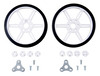
Video: Installing Multi-Hub Wheels
- 31 October 2018This short video shows how to install one of our multi-hub wheels on a motor. These wheels are currently available as an 80×10mm black pair and an...
3 comments


Unfortunately, I no longer have the original code I used for the eyes. However, I can give you a basic outline of what I did. You want to make a loop that reads the sensors and directs the servos to move accordingly. To read the time of flight sensors, use our VL53L0X library for Arduino. The readings should be combined in a way to give the location of an object in front of the sensors. I took each sensor reading and converted them so that the value is bigger the closer the reading is to the sensor. Then I made one negative and added the two values together. That way a value of zero is center, positive denotes one direction and negative another direction. Then I used that location and translated it into a servo position. Then use the commands from the Arduino Servo library to set the position of the servos accordingly.
Post a comment


Home | Forum | Blog | Support | Ordering Information | Lists | Distributors | BIG Order Form | About | Contact
© 2001–2026 Pololu Corporation


