Pololu Blog »
New 5V step-up/step-down voltage regulator S9V11F5
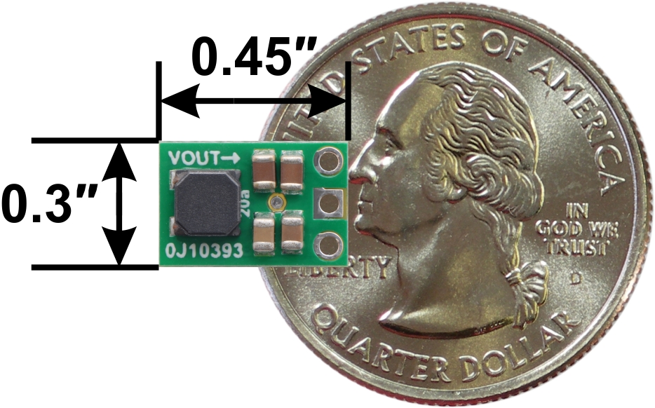 |
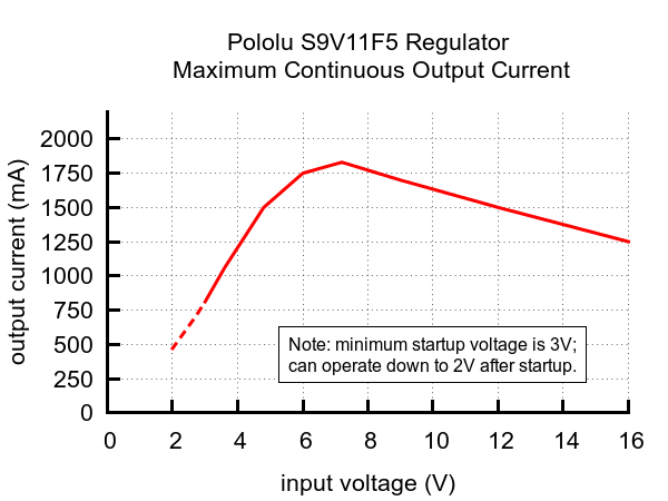
Our newest step-up/step-down voltage regulator, the S9V11F5, takes input voltages between 2 V and 16 V and increases or decreases that voltage as necessary to produce a fixed 5 V output with a typical efficiency of over 90%. (Note that it requires a minimum of 3 V to start up, but it can operate down to 2 V once it is running.) It can temporarily deliver peaks of around 2 A, and the maximum continuous output current depends on the input voltage as shown in the graph below:
 |
The ability to raise or lower the input voltage makes this regulator especially well suited for battery-powered applications where the nominal battery voltage is close 5 V, such as when using four NiMH cells, since the battery voltage transitions from above 5V to below as the battery discharges. The wide input voltage range is also great for applications where you want a lot of flexibility in power supply choice or for systems powered by alternative energy sources like solar or wind, where the output voltage can vary a lot.
With a wider input voltage range and its ability to deliver more current, the S9V11F5 is a higher-performance alternative to our popular S7V7F5 buck-boost regulator, all while being even smaller in size thanks to its double-sided assembly.
For more information on this regulator, visit the S9V11F5 product page, and for other regulator options, you can take a look at our full selection of step-up/step-down regulators, step-up voltage regulators, and step-down voltage regulators.
Related products


-
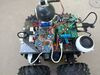
Raspberry Pi, A-Star 32U4, and Wild Thumper robot
- 27 March 2017Forum user coyotlgw made this teleoperated Raspberry Pi robot. The robot is controlled remotely over SSH via the Raspberry Pi’s WiFi connection, and...
-
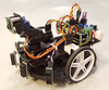
Romi and Raspberry Pi robot
- 28 March 2017Forum user DrGFreeman has been busy making robots. I wrote earlier about his Custom Mini Sumo robot; now here is his Romi Chassis and Raspberry Pi...
8 comments


We do not disclose what IC is used on this regulator. We will be releasing an adjustable version soon, though stock will initially be limited because of component shortages. Please contact us directly with the details of your requirements (output voltage, quantity you need, when you need them, etc.), and we might be able to get you something sooner than the regular release.
-Claire

Thanks!
Tom
We have not characterized the ripple or line regulation for these regulators, but both will depend on the exact details of your system, so if you wanted to be sure they would hold a steady enough 5V for your sensor boards, you would probably have to test them in your setup. If you want the cleanest supply, you might consider boosting from your 5V bus to 5.5V or 6V and then regulating linearly from there. If you have more questions or would like more advice on how these regulators might behave in your setup, I recommend posting more details about it on our forum.
-Claire

You say it gets hot. Can a heat sink be epoxied to the chip and does it increase efficiency?

Depending upon your Arduino it may be possible to use the raw supply along with the USB supply. If you are using an Arduino Uno or an Arduino Mega, the recommended input voltage is 7-12V, so I recommend using our S10V3F9 9V step-up/step-down regulator instead. However, because of the way the power circuit is designed on some Arduinos there can be issues with connecting USB and VIN at the same time. You could potentially power it using 5V on the 5V pin but that would bypass the regulator and would likely damage your board if you connected it via USB while it was powered.
Yes, adding a heat sink should increase the efficiency of that board, although we have not characterized how much it helps.
-Tony

I'm creating a robot with 2 DC motors that will use DRV8835 Dual Motor Driver Kit for Raspberry Pi. The recommended regulator on the driver kit webpage is S7V7F5. After some research I found this one (S9V11F5) which has higher maximum output current. Does S7V7F5 have any advantages over using this one in this kind of application?
Thank you in advance
Pawel

Performance-wise, the S9V11F5 is superior to the S7V7F5. Because it has components on both sides of the PCB, The S9V11F5 might be a tighter fit on the DRV8835 Dual Motor Driver if you plan on mounting it the same way shown on the driver's product page, but it should still be okay as long as you are paying attention to that when you are soldering.
- Patrick
Post a comment


Home | Forum | Blog | Support | Ordering Information | Lists | Distributors | BIG Order Form | About | Contact
© 2001–2026 Pololu Corporation
