Pololu Blog »
How to make a Balboa robot balance, part 4: a balancing algorithm
This is the fourth post in a series about how to make a Balboa 32U4 robot balance. In earlier posts I covered the basic sensors and mechanical parts used for balancing; in this post I will show you how to put everything together to make the robot actually balance.
[See also: Part 1: selecting mechanical parts, Part 2: inertial sensors, Part 3: encoders, or Part 5: popping up and driving around.]
From earlier posts we have obtained six basic variables for use in balancing:
angleRate: the rate of rotationangle: the angle relative to verticalspeedLeft,speedRight: motor speeddistanceLeft,distanceRight: motor distance
I was not specific about this before, but to get the details of the algorithm right it is important to know the signs of these variables. Here is a diagram showing what I mean by positive or negative angles, as well as driving “forward” or “backward”:
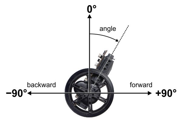 |
Angle convention used by the Balboa 32U4 balancing example. |
|---|
These signs are consistent with the ``y`` angle drawn on the PCB silk screen and the Balboa library’s motor drive functions, as long as you soldered your motors according to the instructions. So now let’s look more at how these variables work.
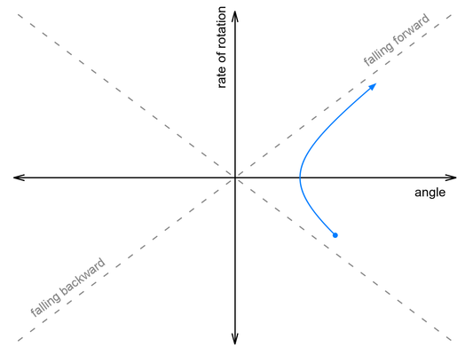
Motor speed and distance are easy enough to understand, since they just measure the effects of applying power to the motors, but the angle variables are related to gravity in a way that is not as intuitive. For the angle variables, I find it helpful to make some plots showing the trajectory of the robot over time. Suppose we take a Balboa with its motors off, start it leaning forward, and give it a little push toward vertical. Initially, angle is positive and angleRate is negative. As the robot rises toward vertical, angleRate decreases until it runs out of momentum, stops, and starts falling forward. It continues to fall forward, faster and faster, until it hits the floor. The blue curve in the graph below shows approximately what the trajectory looks like:
 |
Now suppose we push it harder, so that it falls over onto its other side. This time, it continues rotating as it passes through vertical, then falls backwards onto the floor:
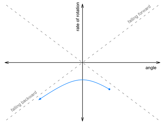 |
Somewhere between these two paths lies a perfectly-balanced trajectory, indicated by the gray dashed line. If we could give it the exact right push, it would follow that line, rising up to vertical just as the rate of rotation falls to zero, and remain balanced forever.
This snippet of code from our Balancer example project computes how far off we are from this ideal rising trajectory:
  // This variable measures how close we are to our basic
  // balancing goal - being on a trajectory that would cause us
  // to rise up to the vertical position with zero speed left at
  // the top.  This is similar to the fallingAngleOffset used
  // for LED feedback and a calibration procedure discussed at
  // the end of Balancer.ino.
  //
  // It is in units of millidegrees, like the angle variable, and
  // you can think of it as an angular estimate of how far off we
  // are from being balanced.
  int32_t risingAngleOffset = angleRate * ANGLE_RATE_RATIO + angle;
In the code, ANGLE_RATE_RATIO is a constant that must be determined through experiment. (A value of 140 worked well for the units we used and our Balboa’s configuration.)
When a Balboa is actively balancing, it “pushes” itself by adjusting the speed of its motors. When the motors make a sudden change in speed, they give a push to the chassis (the combined effect of direct motor torque and of the horizontal motion of the wheels). The effect on the angle variables is the same as if you pushed the chassis by hand: the rate of rotation suddenly changes.
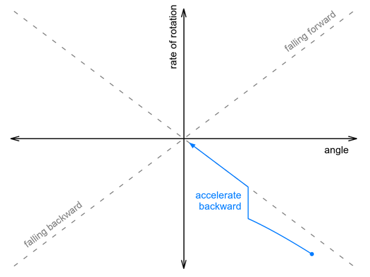
If you think about it a little, you should see that applying backwards acceleration makes the rate of rotation increase (in the positive direction). So how could a Balboa on a trajectory like the one above save itself? It needs to apply just enough backwards acceleration to bump it up onto that ideal dashed gray line:
 |
We don’t know the exact relationship between acceleration and change in rate of rotation, and acceleration is not actually instantaneous, but the basic point is that we should adjust our motor speed by a factor proportional to the risingAngleOffset variable determined earlier. Here’s approximately how we do that in our code:
  int32_t risingAngleOffset = angleRate * ANGLE_RATE_RATIO + angle;
  motorSpeed += ANGLE_RESPONSE * risingAngleOffset;
In this case ANGLE_RESPONSE is a constant that needs to be adjusted experimentally until the robot can “catch” itself from a variety of starting conditions, ending up as vertical as possible.
But what happens after the robot catches itself? It reached a balanced position by changing the motor speed, so now the motors are driving off in some direction. It is balanced, so there is no reason for it to accelerate or decelerate, and it will drive away until it bumps into something or falls down, which is clearly not ideal behavior.
That’s where the encoder-based variables come in to play. We can prevent the robot from driving away by adding additional adjustments to the motor speed that depend on the speed and distance varaibles. Counterintuitively, the way to stop it from driving away in one direction is to accelerate even faster in the same direction, causing it to fall back toward where you want to be. Two additional terms are enough to get it to come back to its starting point:
  int32_t risingAngleOffset = angleRate * ANGLE_RATE_RATIO + angle;
  motorSpeed += ANGLE_RESPONSE * risingAngleOffset
    + DISTANCE_RESPONSE * (distanceLeft + distanceRight)
    + SPEED_RESPONSE * (speedLeft + speedRight);
Again, each variable is multiplied by a constant that must be calibrated experimentally. Of course there is a lot more code required to put everything together; you can see the details in our balancer example on GitHub. Here are some additional considerations addressed in the example code:
- The two motors will have different responses, especially at low speeds where friction is important. So we adjust the power applied to the left and right motors depending on the difference between
distanceLeftanddistanceRight. - To get the units to work out when all the variables are integers, the motor speed needs to be divided by a large number, approximately 10,000. (Alternatively, we could have written each term above as a division, like
risingAngleOffset / ANGLE_RESPONSE, but I think that makes the parameters harder to understand.) - In the example we include a configuration parameter
GEAR_RATIOto make it easier to adjust everything to be approximately right at a different gear ratio. - As mentioned in the last post, this works best if run at a regular interval. The example code takes care of running the algorithm once every 10 ms.
The final result is similar to a PID algorithm, but it responds to both rotational and translational motion with a single output, the motor speed. You can probably get similar results just by starting with the angle and distance variables, creating all six possible PID terms, and adjusting their constants to optimize the motion, but it can be hard to get so many constants right at the same time without a clear understanding of what each one means.
The following video shows our balancing algorithm in action:
The yellow, green, and red LEDs visible in the second part of the video display what the Balboa thinks of its state, with each of the eight possible color combinations indicating a different eighth of the graph. The figure below shows the LED colors in each section of the graph along with the approximate trajectory of the robot after being pushed, so that you can try to follow along with the video:
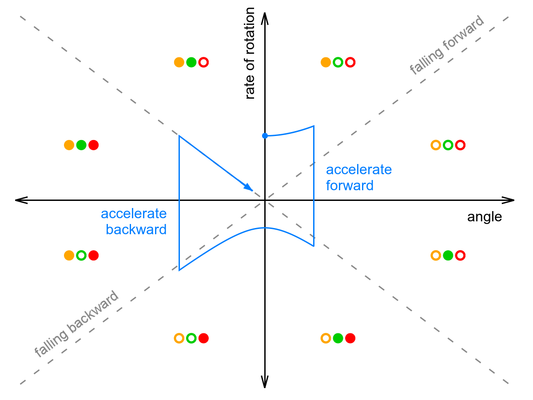 |
One thing you can see from the graph is that the amount of forward acceleration and backward acceleration are about the same, so that overall effect is to drive forward then decelerate to a stop. It’s also important to note that the graph makes it look like the robot only does two large corrections, while in reality it is constantly making small adjustments to the motor speed. Its actual trajectory might look like a smoothed-out version of the blue line, without sharp corners.
There is something major in the video that I have not yet covered: “popping up” from a lying-down position. I will talk about that next week!
Continue reading with Part 5: popping up and driving around.
Related products

-
Arduino library for Sharp distance sensors
- 6 April 2017Julien de la Bruère-Terreault (also known as DrGFreeman on the Pololu Forum, creator of the Custom Mini Sumo robot and the Romi and Raspberry Pi...
-
Balancing robot with stepper motors
- 10 April 2017One of our customers built this six-foot tall balancing robot. The main microcontroller is a Teensy 3.6, and the stepper motors are driven by...
5 comments

I study in a two balancing robot. I want to make this robot move from position A to position B ? How can i can do ? and thanks.

Part 5 of this series discusses driving around. Please also see the comments for some more suggestions.
-Paul

I can get my balboa with arms installed to balance, if I start it standing up, but it will not stand up from a 90 or 85 degree angle lying down.(the angle the robot rests at lying down with the arms installed.)
I have been changing these values in Balance.cpp:
if (angleRate > -2 && angleRate < 2)
{
// It's really calm, so we know the angles.
if (imu.a.z > 0)
{
angle = 110000; changed to 90000 or 80000
}
else
{
angle = -110000; changed to -90000 or -80000
}
distanceLeft = 0;
distanceRight = 0;
}
}
I am I on the wrong track?
I cannot get the red led on with the initial standup code to engage when I press button A.
What part of the balance program “sees” the resting angle when the robot is face down at 110 degrees?
Where should I look to change it to about 87 degrees?
Hey, with further sleuthing of code I’m guessing… are you folks reading the accelerometer values in Balance.cpp?
It seems like there is testing if there is greater than 0 values in Z at rest . and a test with the x axis to run the standup code. I’m I right? Is it possible these tests are not > 0 at 90 degrees?
thanks in advance.

We posted a response to your questions here on our forum.
Please continue the discussion there if you have further questions.
-Nathan
Post a comment


Home | Forum | Blog | Support | Ordering Information | Lists | Distributors | BIG Order Form | About | Contact
© 2001–2026 Pololu Corporation
