Pololu Blog »
How to make a Balboa robot balance, part 2: inertial sensors
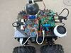
This is the second post in a series about how to make a Balboa 32U4 robot balance. Last week I talked about selecting mechanical components. In this post I will cover the inertial sensors included on the Balboa’s control board and how to use them in your code.
[See also: Part 1: selecting mechanical parts, Part 3: encoders, Part 4: a balancing algorithm, or Part 5: popping up and driving around.]
 |
The key to Balboa’s balancing ability is the built-in ST LSM6DS33 IMU chip, which combines a 3D gyroscope and a 3D accelerometer. The Balboa also includes an ST LIS3MDL 3-axis magnetometer. Both sensors are connected to the AVR via I²C, giving it access to a total of nine sensor channels. These nine channels can be used in software to make an AHRS (attitude and heading reference system), a system that gives the robot a sense of its orientation in three dimensions. AHRS software is particularly important in aviation/drone applications, but for basic balancing, you don’t need anything that complicated. In fact, a single gyro channel is enough to determine the robot’s angle of rotation relative to vertical. The gyroscope’s y-axis channel measures the Balboa’s forward/backward rate of rotation; that is the channel we will be looking at here.
Configuring the gyro
When using the LSM6DS33, the first thing you need to do is configure its angular rate measurement range, which can be set to ±125, ±245, ±500, ±1000, or ±2000 degrees per second. A larger range can support faster motion, but it will have lower resolution. So which range is best for Balboa? If you watch our slow-motion video, you can see it making its quickest movement: popping up 90° from the ground to a balancing position in about a quarter-second, corresponding to an angular speed of around 360°/s. This means that a range of ±1000 is probably enough to cover any normal Balboa motion.
The Pololu LSM6 Arduino library initializes the device with a default setting of ±245°/s, so we have to adjust this in our code. Configuring the LSM6DS33 involves setting some bits in configuration registers, which can be confusing if you have never done it before. You will need to open up the datasheet (1MB pdf), which is also available as a download on the resources tab of the Balboa product page. Let’s look at the table from the datasheet showing the gyro configuration register CTRL2_G:
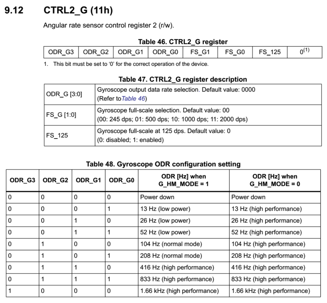 |
Table 46 shows that CTRL2_G is a single byte and tells use the names of each of its bits: ODR_G3, ODR_G2, and so on. The last bit is unnamed but must be set to a “0”. In Table 47 we see that two of the bits, FS_G1 and FS_G0, control the range setting: we need to set them to 1 and 0, respectively, to get ±1000°/s. The FS_125 bit should be left at zero except for ±125°/s mode. The rest of the bits control “data rate”, which has a small effect on the power usage and maybe also sensor noise. We will set it to 208 Hz, since that should be fast enough for our measurements. Looking at the appropriate line in Table 48, we can read off the required bits of ODR_G [3:0]: they need to be set to 0101 for 208 Hz.
Putting this all together, we want to set the CTRL2_G register to a binary value of 01011000, which we can represent directly in C++ as 0b01011000. The LSM6 Arduino library gives us a method for writing to a configuration register over the I²C interface and also includes constants for all of the registers listed in the datasheet, so the rest of the initialization code is easy to write:
void setup()
{
  // Initialize IMU.
  Wire.begin();
  if (!imu.init())
  {
    while(true)
    {
      Serial.println("Failed to detect and initialize IMU!");
      delay(200);
    }
  }
  imu.enableDefault();
  imu.writeReg(LSM6::CTRL2_G, 0b01011000); // 208 Hz, 1000 deg/s
}
Gyro units
After initialization, the sensor will be ready to take readings, which it returns as sixteen-bit signed integers, one for each axis of rotation. Normally, we would talk about the rate of rotation using familiar units such as degrees per second, but the LSM6DS33 uses a different representation. Page 15 of the datasheet shows the sensitivity at each setting:
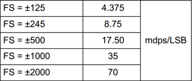 |
LSM6D33 gyro range settings and sensitivity. |
|---|
What this means is that for our setting of ±1000°/s, you can get the rate of rotation in millidegrees per second by multiplying the sensor value by 35. But don’t do that! Since the measurement is a sixteen-bit signed integer, it has a range of -32,768 to +32,767. Multiplying a relatively large value such as 10,000 by 35 will result in an overflow, giving undesirable and even undefined behavior. We could get around this, but for our purposes it’s good enough and safer to instead convert to degrees per second. Mathematically, you would do this by multiplying by 0.035, but that’s also a bad idea in an Arduino program, since bringing floating-point numbers into your program can dramatically increase program size and slow down computations. Instead, since 1/0.035 is about 29, we can divide by 29 to convert to approximate degrees per second. Dividing by a positive, non-zero integer is always safe and cannot generate an overflow.
Testing and calibration
As a check to make sure we are on the right track, this would be a good time to write a test program that shows us gyro data. Please make sure that you have gone over the sections in the User’s guide on assembling your Balboa and programming it, and that you have tried some of the examples in the Balboa32U4 library, then copy this gyro testing code into your Arduino IDE:
#include <Balboa32U4.h>
#include <Wire.h>
#include <LSM6.h>

LSM6 imu;

void setup()
{
  // Initialize IMU.
  Wire.begin();
  if (!imu.init())
  {
    while(true)
    {
      Serial.println("Failed to detect and initialize IMU!");
      delay(200);
    }
  }
  imu.enableDefault();
  imu.writeReg(LSM6::CTRL2_G, 0b01011000); // 208 Hz, 1000 deg/s
}

void loop()
{
  imu.read();
  Serial.println(imu.g.y / 29);
  delay(100);
}
This code reads the gyro ten times per second, displaying the result on the Serial monitor. Here’s some example output for a Balboa that was initially lying down; I rotated it gently up a bit and then back down again:
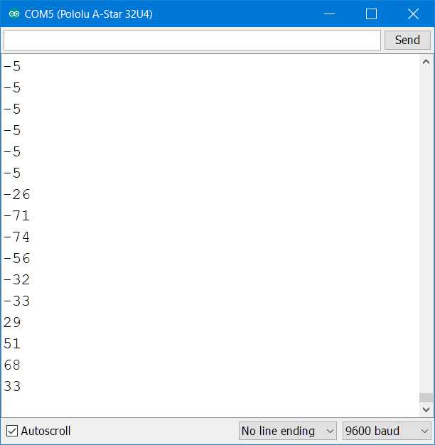 |
The first thing you should see is that the numbers look like useful data: even gentle motion is enough to make them jump up and down a lot, since 1 degree per second is very slow. It’s probably fine that we are using units of degrees per second rather than millidegrees per second. Next, notice that when the robot is at rest, unless you are lucky, the gyro reading is not zero. On my Balboa, the value was -5°/s. According to the LSM6DS33 datasheet, this is to be expected, and it comes largely from stresses placed on the chip when it is soldered. We will have to calibrate the sensor to compensate for this offset in our program. In this case, I could just stick a +5 somewhere in my code, but it’s better to check the offset every time, in case it changes with time or temperature, and to do it in the original units for slightly better accuracy. We can assume that the robot begins at rest and average together a series of 100 measurements for calibration, by defining a global variable gYZero and inserting this code at the end of setup():
  // Wait for IMU readings to stabilize.
  delay(1000);

  // Calibrate the gyro.
  int32_t total = 0;
  for (int i = 0; i < 100; i++)
  {
    imu.read();
    total += imu.g.y;
    delay(1);
  }

  gYZero = total / 100;
Integration
To keep track of the robot’s total rotation angle, you need to integrate the gyro reading: periodically check the sensor and multiply the rate of rotation by the time period. For example, in the Serial monitor output above, when we got a reading of -26, it was rotating at -21°/s during an interval of 0.1 s. A good estimate of the amount of rotation during this interval is -21°/s × 0.1s = -2.1°.
Here is the main gyro-related code from our Balboa Balancer example, which corrects for the offset, converts to degrees, and integrates the angle continuously:
// Call this every 10ms (UPDATE_TIME_MS)
void integrateGyro()
{
  // Convert from full-scale 1000 deg/s to deg/s.
  angleRate = (imu.g.y - gYZero) / 29;

  angle += angleRate * UPDATE_TIME_MS;
}
Since we are combining degrees per second and milliseconds here, the variable angle has units of millidegrees. Again, we have to be careful about the range of values on these variables; a value of 90,000 for 90° is beyond the range of a 16-bit integer. For simplicity, we use 32-bit signed integers (int32_t) for almost all of our calculations.
Initial angle and drift
Integrating the gyro reading actually only determines the total change in angle. You still need to pick a good starting value. An easy way to do this is to start the robot in a known position; for example you could initialize angle with a value of zero and start the robot from a vertical position. Our balancer example expects the robot to start lying down on its front side, with the angle initialized to 110 degrees.
Even after you have calibrated the gyro and estimated the starting angle, your angle measurement will tend to drift over time, maybe a few degrees in a minute. In a full AHRS, you use the accelerometer to eliminate drift, but for a balancing robot we can use a simpler trick: if the robot is successfully balancing, we know that on average, it must be close to vertical. So if we constantly, gradually shift the angle variable towards zero, it will not build up any significant error due to gyro drift. In our balancer example, that just takes a single line of code, called whenever the robot is balancing:
angle = angle * 999 / 1000;
(In a future post, I will talk about how to do this within a complete balancing algorithm, which will have a concept of whether it is currently balancing or lying down.)
Putting this all together, we now have reliable measurements of the robot’s angle and rate of rotation, which will be crucial inputs into our balancing algorithm. Next week I will write about the encoders, another important set of inputs.
Continue reading with Part 3: encoders.
Related products


-
Beefy arms for Balboa balancing robot
- 24 March 2017If you’re following Paul’s blog series about getting your Balboa robot balancing, you’ll probably want something to protect it when it falls. When...
-
Raspberry Pi, A-Star 32U4, and Wild Thumper robot
- 27 March 2017Forum user coyotlgw made this teleoperated Raspberry Pi robot. The robot is controlled remotely over SSH via the Raspberry Pi’s WiFi connection, and...
2 comments

I did have a question about the while(true) in setup()? Should if be while(!imu.init())? Seems like if the sensor didn't come up in the first pass it might come up with a subsequent one?

Post a comment


Home | Forum | Blog | Support | Ordering Information | Lists | Distributors | BIG Order Form | About | Contact
© 2001–2026 Pololu Corporation
