Pololu Blog »
New MOSFET-based power switches
I am excited to announce four new general-purpose MOSFET-based power switches. But why is Pololu making something as seemingly basic as power switches?
Powering your project
One of the most basic requirements for any electronics project is a way to turn the power on and off.
For a typical project assembled on a breadboard, your first approach might naturally be to plug in some breadboard-compatible switch like this:
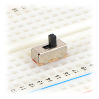 |
This will work okay in many situations, but if you start connecting motors or other high-power components like a Raspberry Pi, you will quickly reach the 300 mA limit of that little switch and melt it or worse. So, assuming that the rest of your project survived, the next step might be to upgrade to a beefier switch:
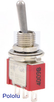 |
I use this one on a lot of projects; it feels really solid and can do 5 A. But it is not breadboard compatible, it is kind of big (more than one inch long), and flipping it takes a lot of force, all of which means more wiring and mounting issues to deal with. And then your project ends up not looking particularly modern – can you imagine a smartphone with one of those sticking out the side? We expect everything these days to be controlled by a tiny pushbutton, with software power features like auto-shutoff. Even my new car does not have the traditional mechanical keyswitch: those are getting rapidly replaced by intelligent software-controlled pushbuttons.
MOSFET-based power switches
With a modern power switch like the one on your phone, the pushbutton itself is only momentary and does not actually conduct the current that powers the device. Typically the button is just an input to a low-power microcontroller that activates MOSFETs as necessary to control power to the rest of the circuit. Programming a microcontroller is a fine approach to power management, but it is a difficult engineering challenge itself. What if you just want a component that does the job for you, like the switches pictured above? That’s where Pololu power switches come in.
|
|
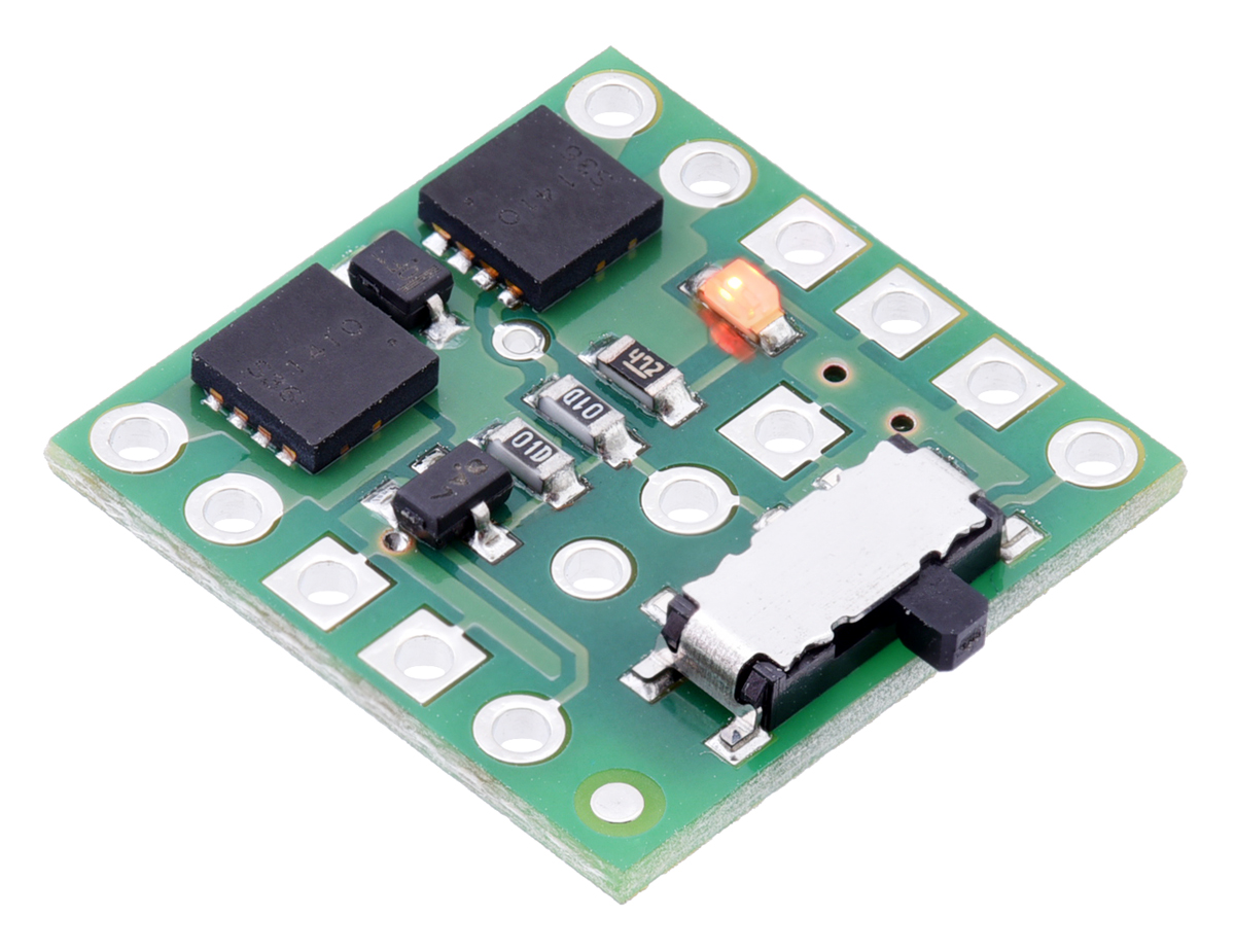
Our power switches do MOSFET-based switching using simple electronic circuits; not having a built-in microcontroller means they are inexpensive and can work over a wide voltage range, for use in a variety of projects. Unlike many soft-power solutions, they are also designed to turn completely off – no current flows in the off state except whatever can leak through the transistors (around 10 nA or less).
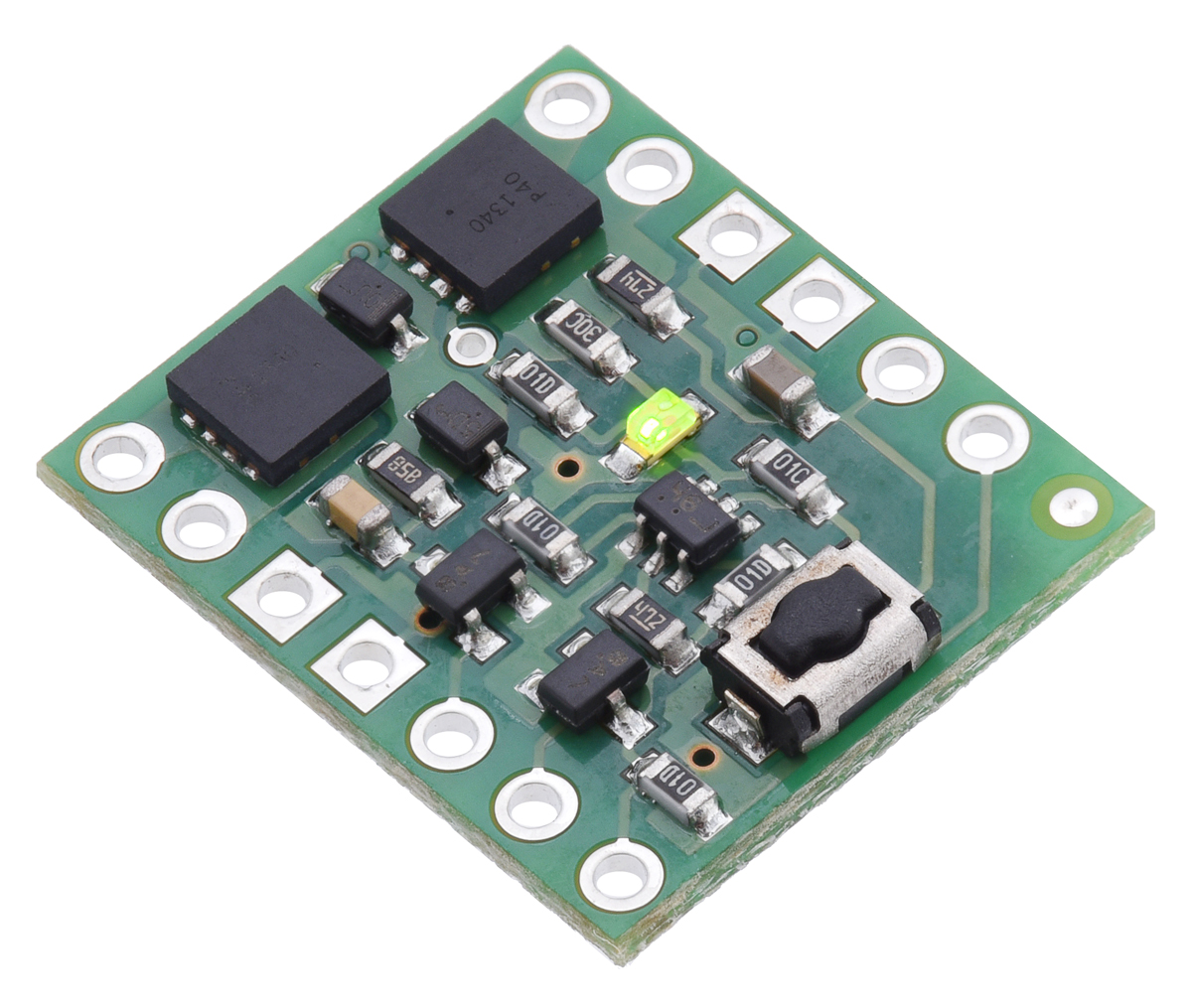
We have been selling switches like these for a long time, both as discrete boards and incorporated into other products. As shown in the pictures above, we have two basic implementations:
- A slide switch that directly controls a MOSFET: the board stays permanently off or on depending on the state of the switch. (Used on the Zumo robots and the A-Star 32U4 Robot Controller.)
- A momentary button for push-on/push-off control, using a latching circuit. (Used on several Orangutan robot controllers and the 3pi robot.)
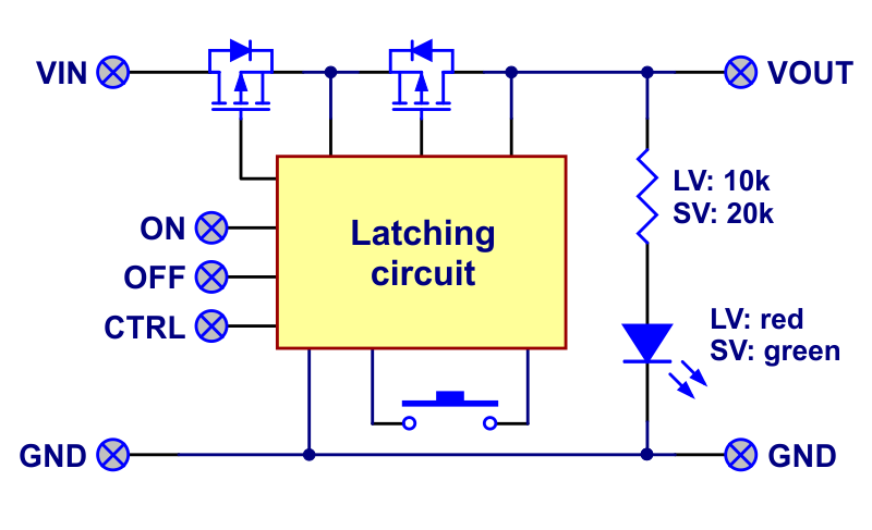 |
Block diagram of the Mini Pushbutton Power Switch with Reverse Voltage Protection. |
|---|
The pushbutton version seems more modern and lends itself better to features like software shutoff, but using it on the 3pi demonstrates one potential disadvantage: if a 3pi crashes into something hard enough to rattle the batteries, the input voltage briefly drops to zero and turns off the switch, stopping the robot. You might consider this a feature, since it prevents further damage to an out-of-control robot. However, when we designed the Zumo, we knew that slamming into things would be standard practice, and a power shutdown in the middle of a sumo match could be disastrous. So our Zumo boards use the slide-switch method of power control.
The new Pololu power switches
Our older pushbutton power switches have long been in need of an upgrade, and now we have two new boards to replace them as well as two entirely new slide-switch versions. The boards have a greatly increased input voltage range: 2.2 V to 20 V on the LV versions or 4.5 V to 40 V on the SV versions, and there are a few other new features:
- An additional MOSFET for reverse voltage protection. This helps protect your project against plugging in batteries or a power supply backwards, making a Pololu power switch a great first stage for your project. Please note that it can’t protect you against shorts that bypass the switch. (Ground connections through a benchtop power supply and a USB cable can cause problems, for example.)
- Control pins that allow your microcontroller to turn the switch on and off. The simpler slide-switch versions just have a single input that turns the switch on, while our pushbutton switches provide inputs for latching the switch either on or off as well as an input (CTRL) that can assert either state.
- Additional connection points so that you can connect your own button or switch (e.g. wire it to the outside of your case) in addition to the pre-installed one.
Note that the form factor is different and the current limits are lower than our older pushbutton power switches, so these are not drop-in replacements.
In summary, don’t be one of those people who has to plug and unplug wires to turn his project on and off. Take a look at the detailed specifications on product pages to select the right switch for your application!
Related products


-
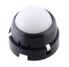
New product: Pololu Ball Caster with 1″ Plastic Ball and Ball Bearings
- 17 September 2015Our ball caster with 1″ plastic ball is now available with ball bearings instead of plastic rollers for even better performance!
-
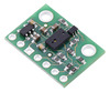
New product: VL6180X Time-of-Flight Distance Sensor Carrier
- 25 September 2015There’s another new product coming out of the assembly line here at Pololu: the VL6180X Time-of-Flight Distance Sensor Carrier. The VL6180 from ST...
20 comments

I guess the only "old fashioned" way might be a relay (i.e. signal relays like the ones used in the telephone business; they need a pulse to change its state and stay in its state w/o power until the next pulse arrives...but they cannot drive much current). Apart from that a Mosfet solution in such an application -i think- is quite elegant.

Our pushbutton power switches have an OFF input which allows a microcontroller powered by the switch to turn off its own power.
-Claire

that's a great product , but i miss a feature , do you have any idea to fix it :
i want the user need to maintain the push for 2 or 3 seconds to turn it off ( to avoid any accident push ) , its better is its only to turn off , but if its for ON or OFF its ok for me .
any 1 have an idea to modify or reflash it ?
thx
thomas
There is no microcontroller in our pushbutton power switch circuits, so they cannot be reflashed, but if your system has a microcontroller in it, you might be able to add an external pushbutton to the A pin on the board and get the behavior you want. A similar application where the user wanted to push a button when their system was off to turn it on, and then detect any additional button pushes with a microcontroller and initiate a power down sequence was discussed in this thread on our forum. You might be able to use the same circuit and program your microcontroller to monitor the button for a few seconds to decide when to turn off.
-Claire

I have a problem with products# 2808 and 2813.
I wanted to use piezo switch with these boards but apparently the impulse is too short.
Sometimes it works to get ON state but it never turns OFF.
Supply voltage 14,8V li-ion battery.
Is there a way to change the reaction of latching circuit to operate with shorter pulses?
I see some resistors and capacitors - my soldering skills are good enough to change these small smd components.
Thank you very much for any advice.

I noticed you also asked about this on our forum . I posted a response; please continue the discussion there.
-Jon

You can supply up to the rated maximum VIN voltage directly to the CTRL pin on our pushbutton power switches (20V for the LV and 40V for the SV, MP, and HP) as long as you do not exceed the voltage you are supplying to VIN. Is your supply at least 12V? By the way, if you have not already noticed, the internal structure of the control pins on the switch is given in the "Using the Pushbutton Power Switch" section of the product page.
-Claire
-Claire
-Claire

It's going to the field today as part of a stand alone solar/battery powered weather station and water conservation system.
Right now we're using it to turn On & Off a power hungry 4-20mA sensor so it doesn't drain our battery when the unit is not making measurements.
To conserve even more battery power, I'd like to open circuit this module's LED (it's in a closed box so no one will see it anyway).
What do you recommend is the best way to disable the on-board LED (e.g., open its series resistor, remove the LED, cut a trace)?
A cut-able trace would be a nice addition.
This module is very reliable and, of course, I assume responsibility for any change I make on my modules.
- Tony
It is good to hear that you like the slide switch design; thanks for the feedback! You could just remove the LED or cut the trace between its bottom pad and the bottom pad of the resistor to the left of it (when looking at the board with the switch on the bottom edge).
-Claire

Are the Resistors R4 and R5 in Q3 integrated?
I see only 3 R's on the Module, the 2 100k and the LED Resistor.
Problem: I need different Values at the Base Voltage Divider.
(And I am not into SMD Soldering...)
Thanks,
gtf
-Claire

could this work as a reverse polarity protection for a li-ion battery charger or a power bank?
Thanks
Jeff
Yes, one of our MOSFET power switches could be used to add reverse voltage protection to most circuits that fit within the switch's voltage and current ratings.
-Claire


We do not commit to or disclose the MOSFETs or diodes on our power switches; however, if there is specific information that you need about them for your application, please contact us directly and we might be able to help.
- Patrick
Post a comment


Home | Forum | Blog | Support | Ordering Information | Lists | Distributors | BIG Order Form | About | Contact
© 2001–2026 Pololu Corporation
