Pololu Blog »
Amanda's line following robot: Newbie
 |
Many of the engineers and robot enthusiasts here at Pololu competed in the LVBots 2015 line following competition. (For house rules and details about how the competition was judged, see the LVBots line following rules page.) This was my first competition at LVBots, so I thought it was fitting to name my robot “Newbie”. Newbie uses a servo to steer the front wheels, creating fluid movements in and out of turns. At least that was the plan; unfortunately, Newbie had complications.
Concept
Anxious about my first LVBots contest, I wanted to build a robot that was unique. With this in mind, I spent a few days researching various line following steering mechanisms. Usually these turned out to be two-wheeled differential drive robots with a ball caster for stability. Since I rarely saw line following robots with a steering mechanism similar to those found in automobiles, I finally settled on building a line follower with a servo-controlled steering assembly in the front and two drive wheels in the back. One advantage about this concept was that it would allow me to use the Maestro Servo Controller Arduino library, which I had helped develop. Considering that I was set on using the Arduino library for the Maestro, I knew that I had to use an Arduino-compatible microcontroller for central processing. There were a lot of positive aspects about building a servo-controlled steering robot, but I found there was sparse documentation on what to consider when designing something like that. Therefore, I had anticipated that a lot of mistakes would be made, and much would be left to trial-and-error.
Design and parts
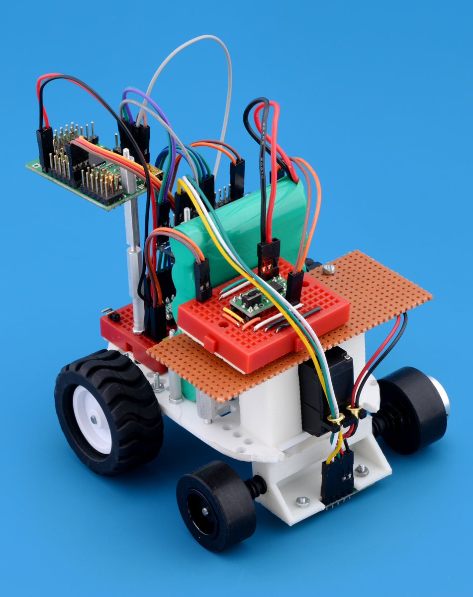
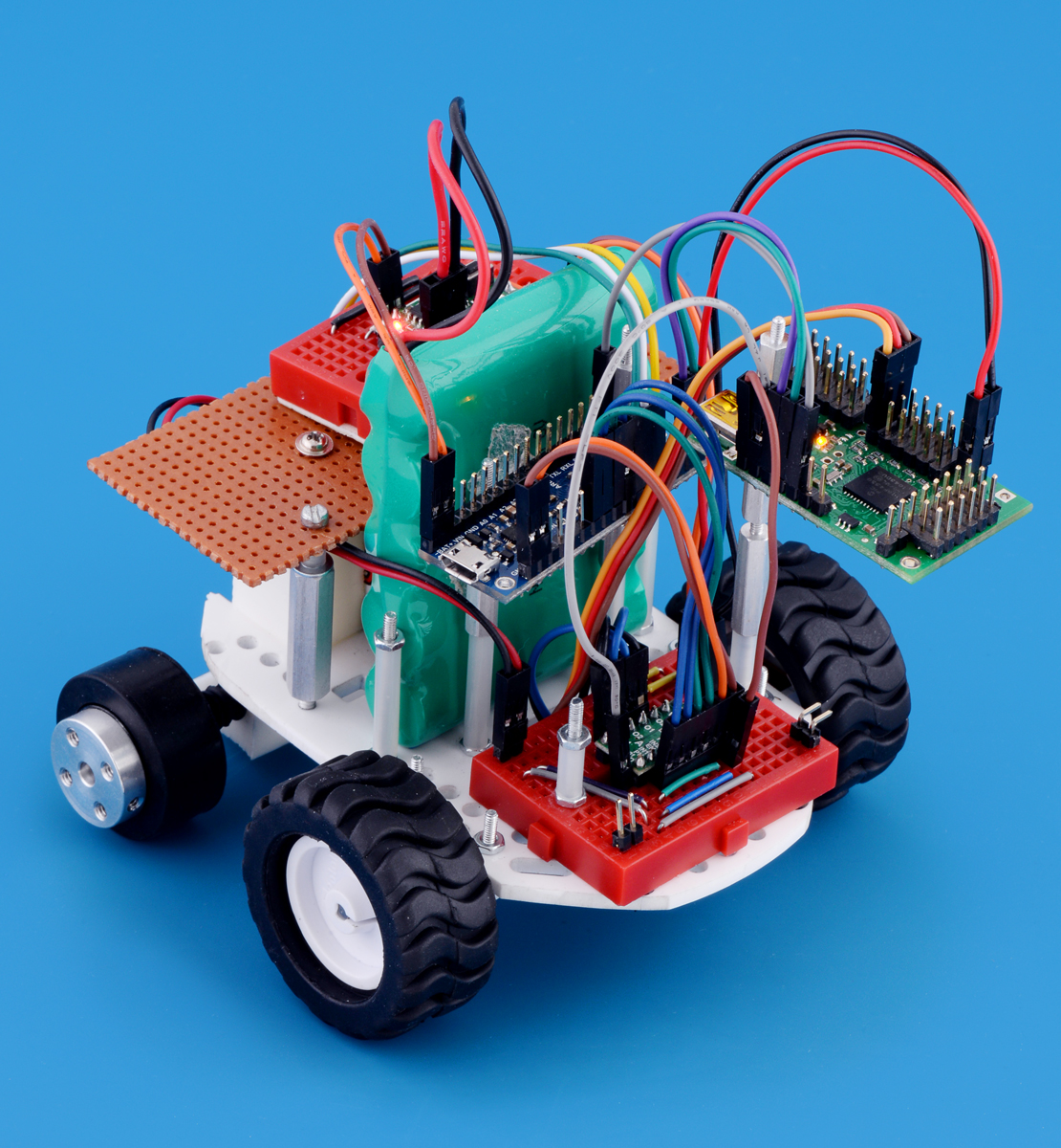
With the competition being a little more than two weeks away, I skipped creating a customized chassis and chose to use Pololu’s precut robot chassis base plate to save time. Unfortunately, whatever time I had hoped to save by getting a precut chassis was instead spent making the part usable (which will be explained in the “Assembly” section). First, the chassis base plate needed to be slimmed down to create a rectangular body, which was necessary to give the servo steering wheels enough room to rotate. Next, focusing on the essential components of a line following robot, I used two 30:1 Micro Metal Gearmotor MP and mounted them onto the chassis using Pololu Micro Metal Gearmotor Extended Brackets. To drive the motors, I decided to use the DRV8835 Dual Motor Driver Carrier for its two motor channels and low operating voltage. Additionally, I could use the DRV8835 Motor Shield Arduino library written for the DRV8835 dual motor driver Arduino shield to control the DRV8835 carrier. Also, I decided to use the A-Star 32U4 Mini LV for its compact size and low operating voltage. For the line following sensor, I picked the QTR-3RC Reflectance sensor, which would fit in-between and in-line with my two front wheels. I choose to install smaller wheels in the front in hopes that the robot would make tighter turns. My first choice was to use the Tamiya 70192 Slick Tire Set, but it was out-of-stock at that time, so I went with the Solarbotics RW2 Wheel instead. As for the servo controller and servo, I reused a Mini Maestro 18-Channel servo controller and a Goteck Mini High-Speed Digital Servo.
|
|
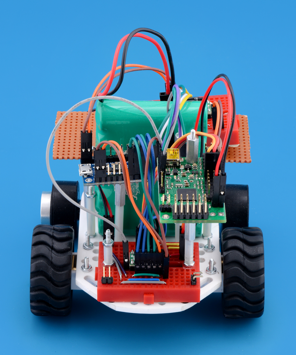
The A-Star 32U4 Mini, Goteck Mini High-Speed Digital Servo and micro metal gearmotors are powered from a single Rechargeable NiMH Battery Pack: 6.0V, 2200mAh. Originally, I was going to power my robot using a LiPo battery, but it was too late to place an order and have it arrive before the competition date.
Assembly
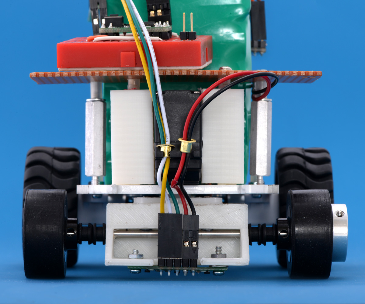
This phase of the project took the longest (a little over a week). Assembly took so long because I had to fit the components onto the chassis base with enough space to attach USB cables to the A-Star and Maestro, find a place for the servo on the chassis base, 3D print parts for the steering and servo mounts, create custom cables to be able to disassemble and reassemble the bot quickly (I was constantly changing the component layout of my robot), map out the turn radius of the front wheels, and scavenge hardware for makeshift mounts so that the components had an optimal layout.
|
|

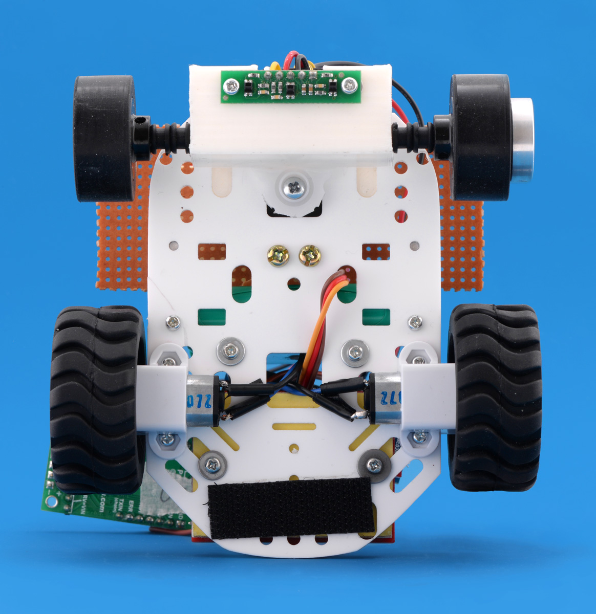
If you are wondering about the Universal Aluminum Mounting Hub on the front left wheel, I added that hub at the last-minute to allow the left wheel to independently rotate from the right wheel. Before this modification, both wheels would only rotate in unison in one direction because they were screwed down onto the 3mm axle shaft.
Outcome
There were a lot of issues with Newbie. The weight and position of the battery pack made Newbie top heavy and unstable, and it did not have a voltage regulator to help maintain performance through each round. However, the biggest issue was Newbie’s body. Primarily, the steering angle was too great compared to the size of the chassis. When the servo position got closer to its configured extrema, the inner front wheel created a lot of drag and caused it to stall – especially through sharper turns. At the last minute, I modified my code to increase the speed of the outer rear wheel and decrease the speed of the inner rear wheel whenever Newbie went into a turn to minimize the drag that the inner front wheel would create. Even though there were lots of problems, I can’t say that Newbie failed in its task after seeing how well it performed in the second round: even though it moved slowly, it completed all three laps.
 |
Improvements
Some definite improvements to Newbie would be to add a regulator, create a steering axle for car-like steering or extend the length of the body (see Ackerman Steering Geometry), customize the chassis base, use a lighter battery pack, and change the layout of the parts to better distribute the weight evenly. Another major improvement would be to come up with an algorithm that will vary the speed of the driving motors in relation to the turning speed of the servo and the radius of the turn.
Related products


-

New distributors in Europe
- 4 June 2015Continuing to catch up on our new distributor introductions, we are excited to welcome these new European distributors: Transfer Multisort...
-
New product: 0.1″ low-profile male LCD header
- 9 June 2015We are now selling the low-profile 2×7 male LCD header included with the Zumo 32U4 robot kit.
2 comments


I do not expect my code to be particularly helpful to you because it is so directly tied to the specific design of my robot, but if you post more details about your robot on our forum, including what you are trying to do and the problems you are having, we might be able to give you some general advice to get you on the right track.
- Amanda
Post a comment


Home | Forum | Blog | Support | Ordering Information | Lists | Distributors | BIG Order Form | About | Contact
© 2001–2026 Pololu Corporation
