Pololu Blog » Engage Your Brain »
Advanced hobby servo control pulse generation using hardware PWM
So far, I have discussed a very simple circuit and a very simple microcontroller approach to generate the control pulses needed to control hobby servos. For some applications, those methods are sufficient, but we often want either to control many servos or to do something in addition to controlling servos, and that is when the limitations of the simple approaches and the demands of the servo interface become more apparent. In this post, I will move on to some more sophisticated techniques to generate servo control pulses.
Here is the diagram I used before of the pulse train we need to generate:
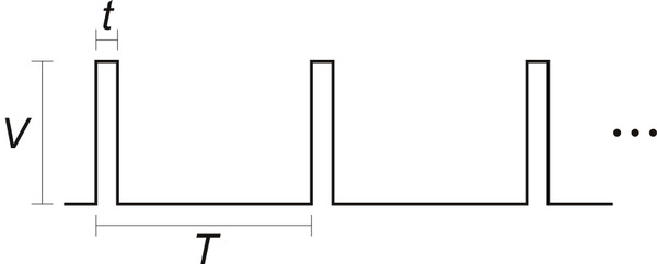 |
Remember, although the waveform looks digital, it is not: the important parameter is the time t that the signal is high, which is called the positive pulse width, and that parameter is effectively an analog, continuous variable. This analog aspect is what makes the interface so unforgiving to a microcontroller: a pulse that is 1.501 ms wide represents a (slightly) different position than a pulse that is 1.500 ms long, and if your pulse width jitters by even that one microsecond, you can see it or hear it in many servos. The extent of the problem can vary with your servo and the load you have on it; I know at least one prominent animatronics company switched from another company’s servo controller to ours because the constant quivering resulting from slight inconsistencies in the pulse width caused their servos to overheat and fail prematurely.
Why does this sensitivity to the exact pulse width matter only when controlling more servos or when doing more than just controlling servos? The answer is that microcontrollers can usually do only one thing at a time. Just making a consistent pulse width while doing nothing else is easy, as we saw last time: all the microcontroller has to do is set a pin high, count to 1500 or whatever, and then make the line low. (If your microcontroller cannot do that extremely consistently, you really should use a different one.) All that changes when we want to do something else rather than just counting to 1500: now, we have to keep track of how much time is going by while doing our second task and then jump back with enough time left to make the pin low at exactly the right time. Some programmers without much microcontroller experience might casually talk about extra threads without really appreciating that we need the accuracy to be better than 1 us. There are various libraries and frameworks and programming approaches that might let you approximate multiple threads, but when you need this kind of timing accuracy, you usually have to plan everything else around it.
To do advanced servo pulse generation, we definitely need some more hardware beyond the basic microcontroller core. The extreme case of this is some true multi-core processor, but that is very uncommon and also inefficient, so that kind of solution is outside of the scope of this discussion. Instead, the extra hardware we will rely on consists of timers and interrupts. These are both very basic and common features of most microcontrollers, but they might not be familiar or available to you if you are working with very beginner-oriented products such as the BASIC Stamp or Arduino. (This is not necessarily a flaw in such products: interrupts are a good way for a beginner to get into trouble and also a good way of taking care of internal or background tasks that a beginner might not want to worry about.) If you are already familiar with these, you can skip these brief descriptions:
- Timers - Timers are peripheral modules that automatically increment counters so that we can keep track of how much time passes while we do various tasks. There are usually various aspects of the timer that can be configured, such as how quickly the timer counts (e.g. every clock cycle, or every four clock cycles), whether it counts up or down, and whether it’s running or stopped. In a very simplified example of how the timer is useful in generating a 1.5 ms pulse, we can start our timer and pulse at the same time, go do something else that we are sure will take safely under 1.5 ms, and then monitor the timer to decide when to end the pulse. Timers are also associated with pulse width modulation (PWM) generation peripherals that I will get to shortly.
- Interrupts - Interrupts allow various events to trigger automatic jumps from normal program execution to interrupt routines, which are special subroutines or functions for dealing with those events. Interrupts can be triggered by things like changes in an input line or when something noteworthy happens with a peripheral module, such as a timer getting to some preset value. When the interrupt routine ends, program execution is supposed to resume at the point where it was interrupted. Interrupts are great and relatively simple if you only need to use one; in our servo pulse example, we can use a timer and its interrupt to end the pulse so that we do not have to keep our eye on the timer as we do our other tasks. However, it usually gets really tempting to use multiple interrupts, and then it’s easy to get into complicated problem situations where you need more than one interrupt routine to happen at the same time.
Using a hardware PWM module
As I mentioned in Servo control interface in detail, I advise against referring to servo control signals as “PWM” (pulse width modulation) signals. However, if we have a flexible-enough PWM peripheral on our microcontroller, we can use it to generate the signals we need. The servo signal has two aspects that make it difficult to generate on some PWM modules. First, the duty cycle is quite low (this means the signal is high for a low percentage of the time). Even if we want only 8-bit resolution (256 positions) in our servo control, we need those 256 positions to correspond to one to two milliseconds out of a 20 ms period, so we need a PWM system that has a resolution of at least 20 times 256, or over 5000 counts. If we allow for faster frequencies, we could get by with the ~4000-count resolution of a 12-bit system, but practically speaking, we usually end up using a 16-bit PWM. The second requirement that takes some PWM peripherals out of contention is that we need a relatively slow frequency of under 100 Hz, whereas most PWM modules are operated at much higher frequencies.
16-bit PWM modules that can operate at around 50 Hz are certainly not rare in the sense that many microcontrollers have them, but unfortunately, they are rare in the sense that there might not be very many of them on one microcontroller. Many popular 8-bit microcontrollers, including Atmel’s AVRs and Microchip’s PICs, have only one 16-bit counter. Even on peripheral-packed 32-bit microcontrollers such as those based on the ARM Cortex cores, more than six 16-bit counters with PWM is a relative luxury that might be available only on high pin-count devices. (Some MCUs offer multiple PWM outputs per single timer, with the restriction that the frequencies and pulse start times are the same, which is not a problem for servo pulses.) If you have a spare 16-bit PWM and you only need to control one servo, or if you have six unused 16-bit PWMs and need to control only six servos, great! In such cases, doing your servo control will be as easy as it can be: just change the PWM value when you want to change your servo position.
In many cases, though, we have fewer 16-bit PWM outputs than we have servos to control. In such a case, we can take advantage of the low duty cycle of the servo interface signal to use an external demultiplexer to distribute the signals from one PWM output pin to several servos. A demultiplexer has an input that can be redirected to one of several outputs based on the values of some selection inputs. I drew a 2-to-4 demultiplexer in the diagram below, but in practice, we can easily extend this for up to eight servos using a part like the 74HC238 3-to-8 demultiplexer, which is easy to get in a DIP package and to use on a breadboard. A benefit of this approach is that only four I/O lines (the PWM pin plus three selection lines) on a microcontroller are needed to control up to eight servos.
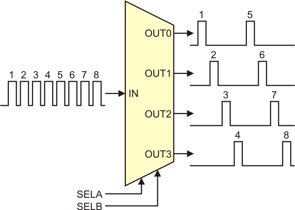 |
The basic idea is that we use the hardware PWM module to generate the pulses for all of our servos on a single line, one after another, and then we use the demultiplexer to send the right pulse to the right servo. We cannot do anything with any of the demultiplexer outputs that are not currently selected, but that does not matter because we just need those lines to stay low between pulses.
In practice, implementing this basic idea is not necessarily trivial, especially if we try to get a lot of performance out of it. What separates this kind of application of a PWM peripheral from some more typical ones is that we care about every single pulse and that we are changing the width of every single pulse. If you are used to using PWM modules to drive H-bridges to drive DC motors, you might not have ever worried about the pulse-by-pulse timing since the whole idea is for the pulses to get averaged out by the motor, and you don’t really need to care if one pulse comes out funny or if there is one more cycle of the old pulse width when you change duty cycles.
PWM modules, like most peripherals, tend to have some kind of buffering to help you prevent unexpected behavior. For instance, when the current pulse width is set to 2.0 ms and you change the value to 1.0 ms right when the pulse is already 1.5 ms long, you usually hope that the current pulse will get completed to the full 2.0 ms and that the next one will be 1.0 ms, with no other pulse widths ever appearing. We also need to make sure we never change the selection lines on the demultiplexer when a pulse is being generated; otherwise, 1.2 ms of our 2.0 ms pulse might end up going to one servo and the remaining 0.8 ms going to another servo. So, if you plan on implementing this kind of servo controller, be prepared to get really familiar with your MCU’s PWM module.
One last thing that I have not explicitly addressed yet is that the whole idea is for us to constrain the main processor as little as possible. Typically, the way to do that would be to use interrupts so that some other tasks are not required to babysit the PWM module. Using interrupts at all is some level of imposition on the rest of the system, but we can mitigate that by making the interrupts as non time-critical as we can so that the interrupts can be of the lowest priority and so that they can even be turned off safely for brief periods. Fortunately, if the pulse width setting is buffered correctly, we can set the next pulse width at any time between the start of a pulse and when the next pulse begins. Our smaller time window is for changing the demux selection pins between pulses, but we can always make that off time bigger if we need it (though that does mean we have to reduce our servo pulse frequency or the number of servos we can control). For instance, if we decide we only need to generate 1-2 ms pulses, we can make the PWM period 3 ms and give ourselves a worst-case time of 1 ms between pulses. If we can generate an interrupt when the pulse ends, we are safe even if it takes a whole millisecond (which is usually an eternity even if you are running at only a few MHz) for the processor to get to our interrupt.
If you want more details about a particular implementation, this is how we do servo control on the Orangutan SVP. You can look at the actual code for an AVR in the Pololu AVR Library.
Conclusion (for now)
This technique lets you control up to eight servos from one 16-bit PWM output; if you have a few of these more capable PWM outputs available, you can relatively easily control two dozen servos (enough for very ambitious hexapod or biped robots) without requiring much of your processor. Next time, I will talk about controlling high numbers of servos without a hardware PWM module and external demultiplexer.
-

Motion simulator chairs
- 21 April 2011Jrk 12v12s are used as part of two-degree-of-freedom motion-simulator chairs (sim chairs) in this project posted to the XSimulator forums. Here...
-
Learning PID values using simulated annealing
- 29 April 2011This is a video of a robot based on the Pololu 5" robot chassis that automatically improves its PID constants over time.
6 comments

intervals. After reading Advanced hobby servo control pulse generation using hardware PWM, would that be a good fit for my project?

I don't know how you expect me to be able to judge that better than you. However, from the little information I can get from your question, it sounds like you aren't getting the point. This article is about a specific approach to getting many channels of servo control. If you just need one or a few servos, you don't need anything this complicated, and if you need to do many servos, you're probably better off getting a dedicated servo controller.
- Jan

This article is about using one PWM source to get multiple servo control signals. As I said in the post, I think it is not helpful to think of servo control pulses as general PWM signals. You cannot get four arbitrary PWM signals out of one PWM signal.
- Jan

The problem is that after a minute or so, the 9 PWM signals produced, go mad for some reason and then after a minute they become normal again. I cannot find a solution to this problem If you want the code and the schematic i made so as to try it , and hopefully find a solution, send me an email at ekostoul@cc.uoi.gr . The circuit works great. I think it has something to do with my code (embedded C). If you find a solution please let me know which were your changes in the code

I am sorry you are having trouble controlling your servos; I think some people on the Pololu forum might be interested in taking a look. I recommend posting to the Software and Microcontrollers section, and including your code as well as oscilloscope traces.
-Jon
Post a comment


Home | Forum | Blog | Support | Ordering Information | Lists | Distributors | BIG Order Form | About | Contact
© 2001–2026 Pololu Corporation


