MC33887 Motor Driver Carrier

This little board is an easy way to use Freescale’s MC33887 DC motor driver. Thanks to a 5-28 V operating range, current output up to 5 A (2.5 A continuous), and extra features such as current sensing and over-current protection, the 33887 is an excellent general-purpose motor driver.
Discontinuation Notice: This board has been replaced by the more capable MC33926 motor driver carrier.
| Description | Specs (12) | Pictures (5) | Resources (2) | FAQs (0) | On the blog (0) | Distributors (0) |
|---|
Discontinuation Notice: This board has been replaced by the more capable MC33926 motor driver carrier.
 |
These compact carriers for the Freescale Semiconductor MC33887 motor driver integrated circuit are an easy way to connect a brushed DC motor running from 5 to 28 V and drawing up to 5 A (peak) to your project. The board incorporates all of the components of the typical application diagram on page 25 of the MC33887 datasheet, plus motor-direction LEDs and a FET for reverse battery protection. All you need to add is a microcontroller or other control circuit to turn the H-Bridge on and off. If you have two motors to control, please consider the Dual MC33887 motor driver carrier. For a very similar motor driver that supports ultrasonic (up to 20 kHz) PWMs and a wider logic voltage range (3 – 5 V), please consider the MC33926 motor driver carrier or Dual MC33926 motor driver carrier.
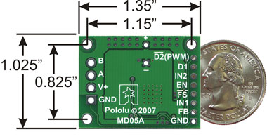
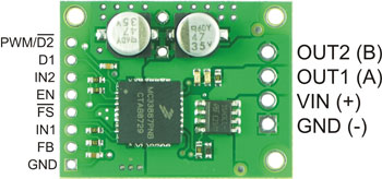
In a typical application, the power connections are made on one end of the board, and the control connections (5V logic) are made on the other end. The enable (EN) pin does not have a pull-up resistor, so you must pull it to +5 V in order to wake the chip from sleep mode. The fault-status (FS, active low) output pin may be left disconnected if you do not want to monitor the fault conditions of the motor driver; if you do connect it you must use an external pull-up resistor to pull the line high. IN1 and IN2 control the direction of the motor, and D2 can be PWMed to control the motor’s speed. D2 is the “not disabled” line: it disables the motor driver when it is driven low (another way to think of it is it enables the motor driver when driven high). Whenever D1 or D2 disable the motor driver, the FS pin will be driven low. The feedback (FB) pin outputs a voltage proportional to the H-Bridge high-side current, providing approximately 0.59 volts per amp of output current.
 |
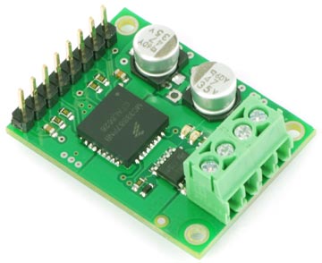
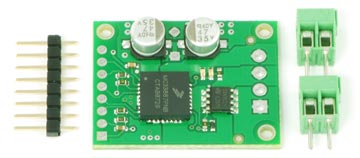
The MC33887 motor driver carrier PCB comes with two 47 uF, 35 V surface-mounted capacitors and holes for installing an additional through-hole capacitor. This third capacitor can be added in conjunction with the two surface-mount capacitors to further limit disturbances on the main power line, or it can be added in place of the two surface-mount capacitors to allow the MC33887 motor driver carrier to function at high voltages.
 |
MC33887 Specifications
- Operating voltage: 5-28 V
- Maximum PWM frequency: 10 kHz
- Current sense: 0.59 V/A
- Time to overheat at 5 A*: 2 s
- Time to overheat at 4 A*: 21 s
- Time to overheat at 3 A*: 165 s
- Current for infinite run time*: 2.5 A
*Typical results using MC33887 motor driver carrier with 100% duty cycle at room temperature with no forced air flow or heat sink.
Real-world power dissipation considerations
The MC33887PNB motor driver used on the carrier board has a maximum current rating of 5 A continuous. However, the chip by itself will overheat at lower currents (see table above for typical values). The actual current you can deliver will depend on how well you can keep the motor driver cool. The carrier’s printed circuit board is designed to draw heat out of the motor driver chip, but performance can be improved by adding a heat sink. In our tests, we were able to deliver 5 A for a few seconds and 2.5 A continuously without overheating. These tests were conducted at 100% duty cycle; PWMing the motor will introduce additional heating proportional to the frequency.
This product can get hot enough to burn you long before the chip overheats. Take care when handling this product and other components connected to it.
Unlike other H-Bridges, the 33887 has a feature that allows it to gracefully reduce current as the current exceeds 5 A or as the chip temperature approaches its limit. This means that if you push the chip close to its limit, you will see less power to the motor, but it might allow you to avoid a complete shutdown.
Schematic Diagram
 |
Note: An 8-pin male header and two 2-pin terminal blocks are included but not soldered onto the boards. No printed documentation is shipped with these items; please see the MC33887 datasheet in the resources tab for more information about the motor drivers.
 |
Related products


Related categories


Home | Forum | Blog | Support | Ordering Information | Lists | Distributors | BIG Order Form | About | Contact
© 2001–2026 Pololu Corporation
