Support » Pololu Zumo 2040 User’s Guide » 6. The Zumo 2040 in detail »
6.5. Front sensor array (line and proximity sensors)
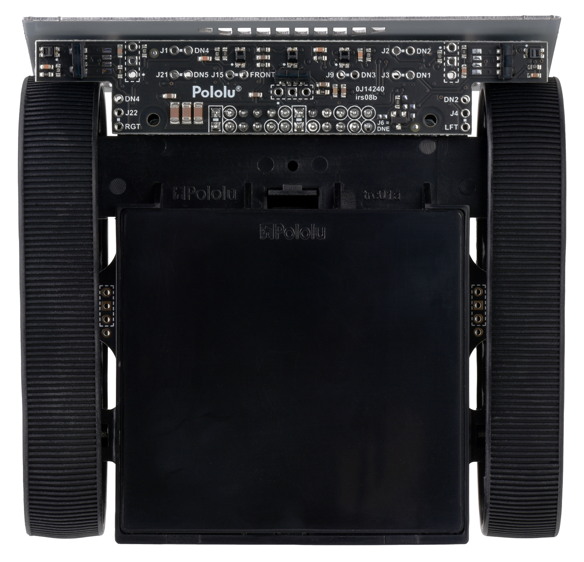 |
The Zumo 2040 Front Sensor Array is a separate board that attaches to the main board. The board features five line sensors and three proximity sensors.
The five line sensors face downward and can help the Zumo distinguish between light and dark surfaces. Each reflectance sensor consists of a down-facing infrared (IR) emitter LED paired with a phototransistor that can detect reflected infrared light from the LED. The reflectance sensors operate on the same principles as our RC-type QTR reflectance sensors: the RP2040 uses an I/O line to drive the sensor output high, and then measures the time for the output voltage to decay. You can read more about the operating principles of these sensors in our QTR Reflectance Sensor Application Note.
The five line sensors are numbered 1 through 5, with line sensor 1 being the robot’s left-most sensor. In schematics and diagrams, they are referred to as DOWN1, DOWN2, DOWN3, DOWN4, and DOWN5. On the front sensor array, their signals are labeled DN1, DN2, DN3, DN4, and DN5. The infrared emitters for the line sensors are controlled by the DOWNEMIT signal, which is labeled DNE on the front sensor board.
The three proximity sensors face in different directions away from the Zumo and can help detect nearby objects. They can also be used to detect commands from typical IR remote controls. The proximity sensors, like the line sensors, detect reflected IR light, but they are designed to only detect light that is turned on and off quickly at a frequency of 56 kHz. To read a proximity sensor, the RP2040 can enable the internal pull-up on the corresponding I/O line. When the sensor is active, it will drive the line low. The proximity sensors do not have IR emitters paired with them; instead they detect reflected 56 kHz IR light that comes from LEDs on the Zumo 2040 Main Board, which are described in Section 6.6. The proximity sensors are named after the directions they face: left, right, or front. In schematics and diagrams, they are referred to as LEFT, RIGHT, and FRONT. On the front sensor array, their signals are labeled LFT, FRONT, and RGT.
Each sensor output on the front sensor array is protected by a 220 Ω resistor to help prevent short circuits when the RP2040 is driving the corresponding I/O line.
The infrared light emitted by the line sensors can interfere with the proximity sensors and cause false readings, so it is recommended to turn off the line sensor emitters before using the proximity sensors.
The Zumo 2040 Robot Libraries and Example Code provide functions to help with reading the line sensors and proximity sensors, and it handles control of the emitters appropriately.
Ambient light considerations
Since the line sensors and proximity sensors rely on measurements of reflected infrared light, they are strongly affected by ambient sources of IR light in the surrounding environment (e.g. sunlight or strong incandescent lighting).
You can help compensate for ambient IR light by incorporating some calibration procedures in your programs. For example, the line sensors can measure the reflectance of light and dark surfaces during calibration and then report subsequent readings relative to this range. The Zumo 2040 libraries provide support for calibrating the line sensors in this way.
However, this calibration is not foolproof; too much ambient infrared light can still prevent the line sensors from working well, and the calibration will not remain effective if the ambient light level changes, such as if the Zumo moves from a brightly lit area to a more shaded area.
Pin assignments and remapping
By default, the front sensor array supports these pin assignments:
- GP26 is connected to the line sensor emitter control pin (DNE).
- GP22 is connected to line sensor 1 (DN1).
- GP21 is connected to line sensor 2 (DN2).
- GP20 is connected to line sensor 3 (DN3).
- GP19 is connected to line sensor 4 (DN4).
- GP18 is connected to line sensor 5 (DN5).
- GP27 is connected to the front proximity sensor.
- GP23 is connected to the left proximity sensor.
- GP24 is connected to the right proximity sensor.
GP26 also doubles as an input to measure the battery level through a voltage divider (see Section 6.7), which uses a ratio low enough that the line sensor emitters will effectively be off while the pin is an input.
The signals from the sensors can be remapped by soldering in a wire from the signal output to the desired GPIO pin. You would also want to disconnect the sensor output from the default GPIO pin so that pin can be used for other purposes. Disconnecting each sensor involves cutting a trace between the signal output and the default GPIO pin, which is labeled according to the position of its pin on the front sensor board’s connector. (For example, line sensor 1 is connected to pin J3, which plugs into GP22 on the Zumo main board.)
GP17 and GP16 are also used for proximity sensing as they respectively control the left and right proximity emitters on the Zumo’s main board, although these two pins do not interface with anything on the front sensor array.


Home | Forum | Blog | Support | Ordering Information | Lists | Distributors | BIG Order Form | About | Contact
© 2001–2026 Pololu Corporation
