Support » Pololu Motoron Motor Controller User’s Guide » 4. Pinout »
4.4. Motoron M3H550 and M3H256 pinout
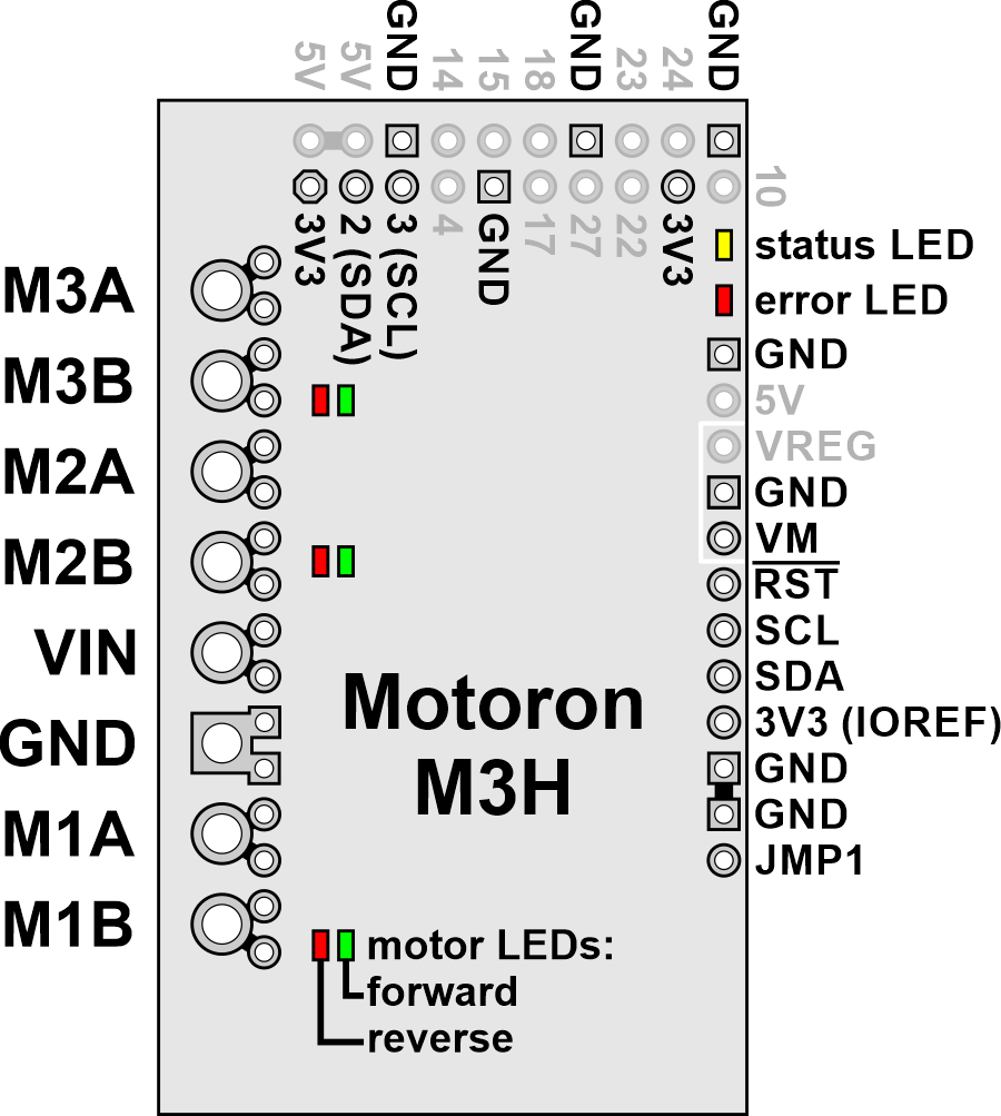 |
The diagram above identifies the control and power pins on the Motoron M3H550 and M3H256. Pins that are used by the motor controller are indicated in black, while pins that are not connected to anything by default are gray. Section 3.2.4 explains how to connect motor power, motors, and a microcontroller.
The motor power supply should be connected to the VIN pin and adjacent GND pin, and a motor can be connected to each pair of MxA and MxB pins (e.g. M1A and M1B). For more information on choosing a power supply and motors, see Section 3.1.
The Motoron’s logic is powered from the 3V3 pin, which connects to the pin of the same name on the Raspberry Pi. The Motoron is controlled via I²C through the SCL and SDA pins (see Section 6). Additional GND pins provide a common ground reference between the Motoron and the Raspberry Pi.
The JMP1 pin can be shorted to the adjacent GND pin to allow the Motoron’s I²C address to be changed, as detailed in Section 3.4. Also, shorting JMP1 to GND at startup causes the Motoron to ignore the address configured in EEPROM and use 15 as its I²C address instead.
The RST pin can be driven low to reset the Motoron; see Section 12 for more details.
The VM pin provides access to the reverse-protected motor supply voltage.
You can optionally power the Raspberry Pi by supplying 5 V to the VREG pin. To help achieve this, the Motoron M3H550 and M3H256 have adjacent VM, GND, and VREG pins which you can connect to a voltage regulator. The regulator should be connected in the correct orientation so that the Motoron’s VM pin connects to the regulator’s power input and the regulator’s power output connects to VREG. The motor power supply must be in the allowed input voltage range of the regulator, and the regulator must output 5 V (or something close enough to be tolerated by the Raspberry Pi). The regulator must also be able to supply enough current for the Raspberry Pi (e.g. 3 A for a Raspberry Pi 4). An ideal diode circuit on the Motoron prevents reverse current from flowing from the Raspberry Pi to the VREG pin if the Raspberry Pi is separately powered (for example, through its USB power receptacle). However, we do not recommend connecting external USB power to the Raspberry Pi while it is powered through the Motoron, since recent versions of the Raspberry Pi (including the 4 Model B and 3 Model B+) do not have a corresponding diode on their USB power input, so it is possible for the Motoron to backfeed a USB power adapter through the Raspberry Pi.
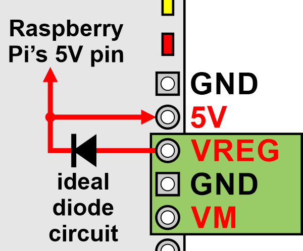 |
Powering the Raspberry Pi’s 5V pin from an external regulator connected to VM on a Motoron M3H550 or M3H256. |
|---|
The 5V pin connects to the pin of the same name on the Raspberry Pi. It is also the output of the ideal diode circuit.
Related products


Related categories


Home | Forum | Blog | Support | Ordering Information | Lists | Distributors | BIG Order Form | About | Contact
© 2001–2026 Pololu Corporation
