Support » Pololu Dual G2 High-Power Motor Driver Shields for Arduino User’s Guide » 4. Board connections »
4.b. Control and feedback pins
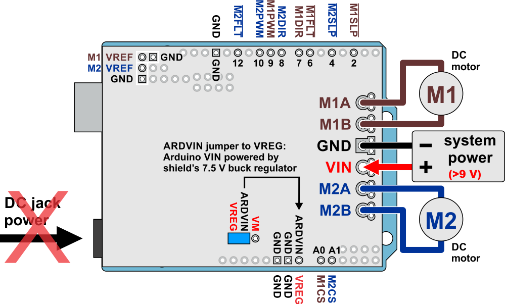 |
Dual G2 high-power motor driver shield powering an Arduino with the shield’s 7.5 V regulator (VREG). |
|---|
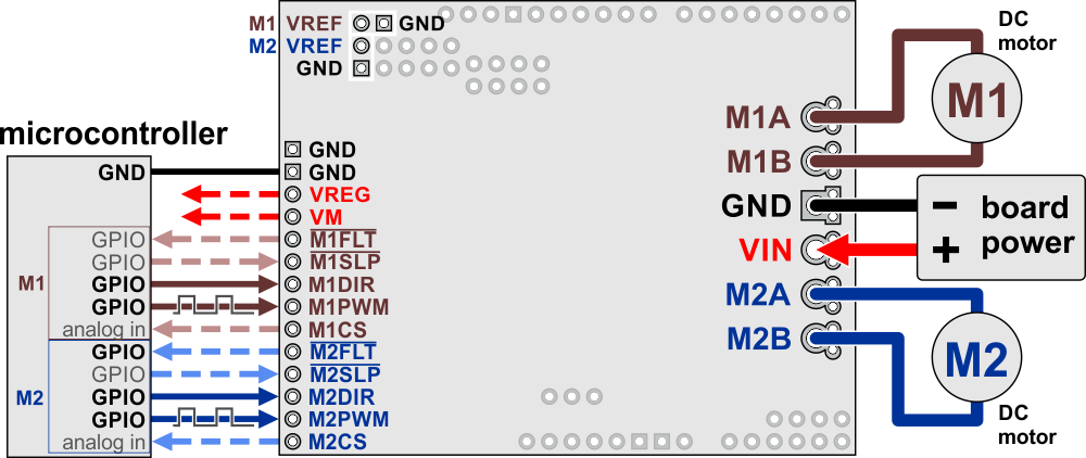 |
Dual G2 high-power motor driver shield connected to a microcontroller (dashed connections are optional). |
|---|
This table explains what the motor driver’s control and feedback pins are and how they connect to an Arduino when the driver is used as a shield:
| Motor driver pin | Default state | Arduino pin |
Description |
|---|---|---|---|
| M1FLT | 6 | Fault indicators: These open-drain outputs drive low when a fault is occurring. In order to use these outputs, they must be pulled up to your system’s logic voltage (such as by enabling the internal pull-ups on the Arduino pins they are connected to). See below for details. | |
| M2FLT | 12 | ||
| M1SLP | HIGH | 2 | Inverted sleep inputs: These pins are pulled high, enabling the driver by default. Driving these pins low puts the motor driver channels into a low-current sleep mode and disables the motor outputs (setting them to high impedance). |
| M2SLP | 4 | ||
| M1DIR | LOW | 7 | Motor direction inputs: When DIR is low, motor current flows from output A to output B; when DIR is high, current flows from B to A. |
| M2DIR | 8 | ||
| M1PWM | LOW | 9 | Motor speed inputs: A PWM (pulse-width modulation) signal on these pins corresponds to a PWM output on the corresponding channel’s motor outputs. When a PWM pin is low, the corresponding motor brakes low (both A and B are shorted together through ground). When it is high, the motor is on. The maximum allowed PWM frequency is 100 kHz. |
| M2PWM | 10 | ||
| M1CS | A0 | Current sense outputs: These pins output voltages proportional to the motor currents when the H-bridges are driving (but not while they are braking, including when current limiting is active). The output voltage is about 10 mV/A for the 18v22 and 20 mV/A for the other versions, plus an approximate offset of 50 mV. | |
| M2CS | A1 | ||
| M1VREF | Current limit threshold adjustments: A resistor can be connected between VREF and the adjacent GND to lower the current limiting (chopping) threshold from its default setting. See below for details. | ||
| M2VREF |
Motor control options
With the PWM pin held low, both motor outputs will be held low (a brake operation). With PWM high, the motor outputs will be driven according to the DIR input. This allows two modes of operation: sign-magnitude, in which the PWM duty cycle controls the speed of the motor and DIR controls the direction, and locked-antiphase, in which a pulse-width-modulated signal is applied to the DIR pin with PWM held high. Our Arduino library for this driver uses sign-magnitude operation.
In locked-antiphase operation, a low duty cycle drives the motor in one direction, and a high duty cycle drives the motor in the other direction; a 50% duty cycle turns the motor off. A successful locked-antiphase implementation depends on the motor inductance and switching frequency smoothing out the current (e.g. making the current zero in the 50% duty cycle case), so a high PWM frequency might be required.
| Inputs | Outputs | Operation | |||
|---|---|---|---|---|---|
| SLP | DIR | PWM | MxA | MxB | |
| 1 | 0 | PWM | PWM (H/L) | L | forward/brake at speed PWM % |
| 1 | 1 | PWM | L | PWM (H/L) | reverse/brake at speed PWM % |
| 1 | X | 0 | L | L | brake low (outputs shorted to ground) |
| 0 | X | X | Z | Z | coast (outputs off) |
PWM frequency
The motor driver supports PWM frequencies as high as 100 kHz, but note that switching losses in the driver will be proportional to the PWM frequency. Typically, around 20 kHz is a good choice for sign-magnitude operation since it is high enough to be ultrasonic, which results in quieter operation.
A pulse on the PWM pin must be high for a minimum duration of approximately 0.5 µs before the outputs turn on for the corresponding duration (any shorter input pulse does not produce a change on the outputs), so low duty cycles become unavailable at high frequencies. For example, at 100 kHz, the pulse period is 10 µs, and the minimum non-zero duty cycle achievable is 0.5/10, or 5%.
Fault conditions
The motor driver can detect several fault states that it reports by driving the FLT pin low; this is an open-drain output that should be pulled up to your system’s logic voltage. The detectable faults include short circuits on the outputs, under-voltage, and over-temperature. All of the faults disable the motor outputs but are not latched, meaning the driver will attempt to resume operation when the fault condition is removed (or after a delay of a few milliseconds in the case of the short circuit fault). The over-temperature fault provides a weak indication of the board being too hot, but it does not directly indicate the temperature of the MOSFETs, which are usually the first components to overheat, so you should not count on this fault to prevent damage from over-temperature conditions.
Current sensing
The current sense output sensitivity depends on the motor driver version: it is approximately 10 mV/A for the 18v22 and 20 mV/A for all other versions. There is an offset of approximately 50 mV, and this can vary some from unit to unit, so we recommend first calibrating the current sense by reading this zero-current offset. Each CS output is only active while the corresponding H-bridge is in drive mode; it is inactive (low) when the channel is in brake mode (slow decay), which happens when the PWM input is low or when current limiting is active. Current will continue to circulate through the motor when the driver begins braking, but the voltage on the CS pin will not accurately reflect the motor current in brake mode. The CS voltage is used internally by the motor driver, so to avoid interfering with the driver’s operation, you should not add a capacitor to this pin or connect a load that draws more than a few mA from it.
Current limiting
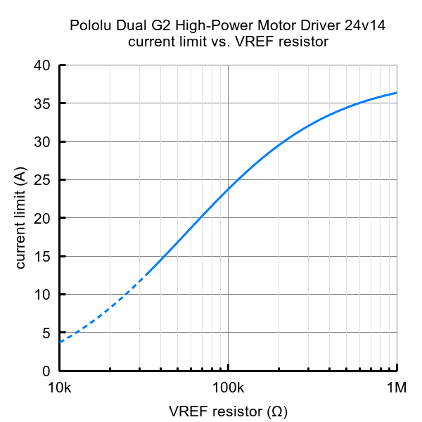
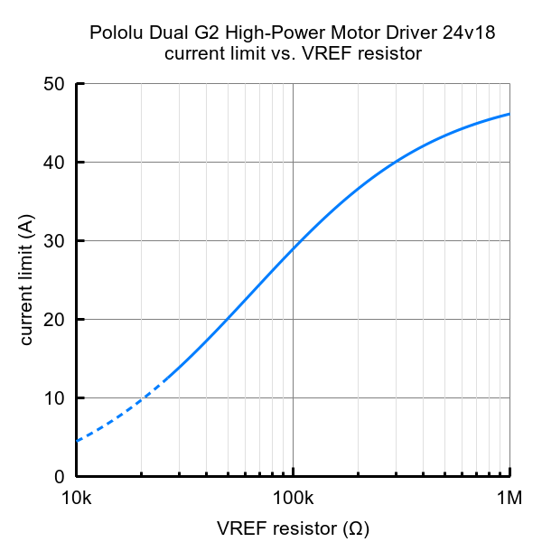
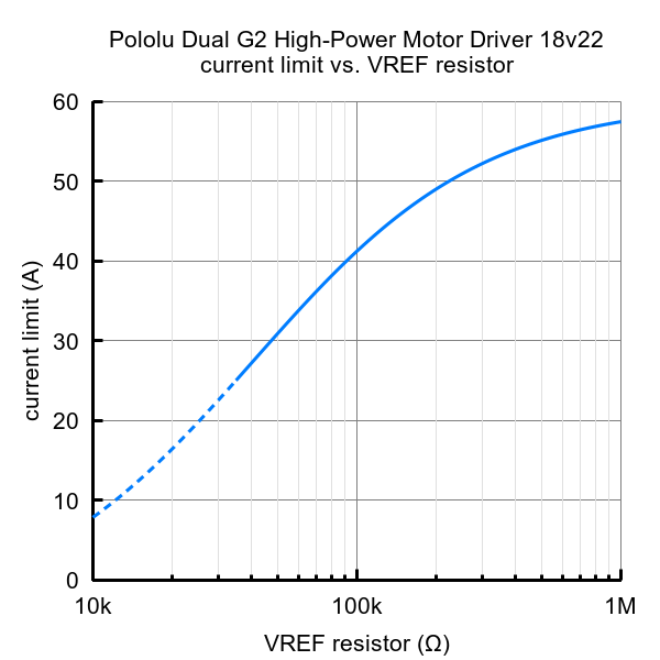
The driver has the ability to limit the motor current through current chopping: once the motor drive current reaches a set threshold, the driver goes into brake mode (slow decay) for about 25 μs before applying power to drive the motor again. This makes it more practical to use the driver with a motor that might only draw a few amps while running but can draw many times that amount (tens of amps) when starting. The default current limiting threshold depends on the version of the motor driver as follows:
- 40 A for 24v14
- 50 A for 18v18 and 24v18
- 60 A for 18v22
This default threshold can be lowered for each channel by connecting a resistor between the VREF pin and the adjacent GND pin. The graphs below (one for each board version) show how the current limit relates to the VREF resistor value. Note that the current limiting threshold is not highly precise, and is less accurate at especially low settings (indicated by the dashed portion of the curve).
 |
 |
 |
 |


Home | Forum | Blog | Support | Ordering Information | Lists | Distributors | BIG Order Form | About | Contact
© 2001–2026 Pololu Corporation
