Support » Pololu Dual G2 High-Power Motor Driver Shields for Arduino User’s Guide » 4. Board connections »
4.c. Remapping the Arduino connections
For some applications, this shield’s default Arduino pin mappings might not be convenient. For example, maybe you want to use the 16-bit Timer 1 for making music on a buzzer and would rather use PWMs from Timer 0 to control your motor speed. Or maybe you don’t care about monitoring the motor current and would rather use all of your analog inputs for reading sensors. With this in mind, we designed the shield to have break points in the connection between the Arduino pins and the motor drivers. It is easy to cut the connections at these points and establish new connections to replace the broken ones if desired.
The connections between the Arduino pins and the motor driver pins are each made through a pair of 0.1″-spaced holes that are connected on the top side of the shield by a thin trace. The following two diagrams show the default pin mapping for motor drivers 1 and 2:
|
|
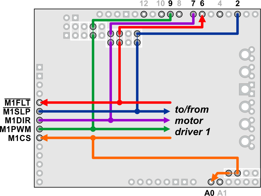
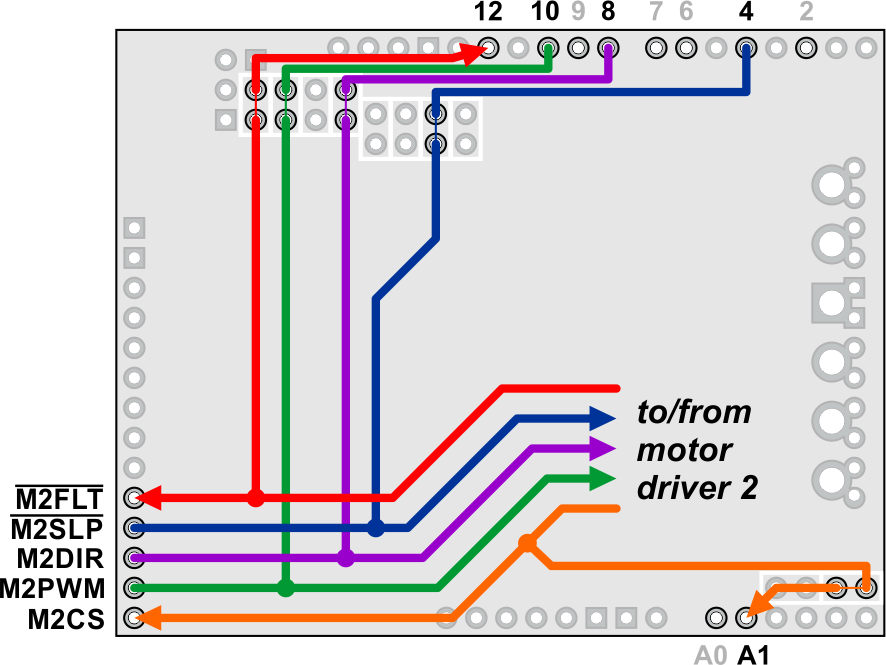
In all cases, the top through-holes of the vertical pairs and the left through-holes of the horizontal pairs connect to the Arduino pin, and the bottom/right through-holes connect to the motor driver pin. To change one of the default mappings, you can use a knife to cut the trace between the appropriate pair of holes on the top side of the PCB (there is no connection to cut on the underside of the PCB) and run a wire from a different Arduino pin to the bottom hole of the pair to create a new connection.
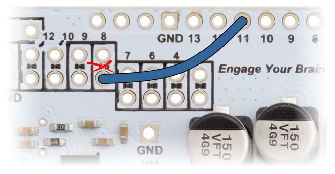 |
Dual G2 high-power motor driver shield remapping example: moving M2DIR from Arduino pin 8 to pin 11. |
|---|
You can later use shorting blocks to restore the default pin mapping if you populate the severed hole pairs with 1×2 pieces of the included 0.1″ male header strip.


Home | Forum | Blog | Support | Ordering Information | Lists | Distributors | BIG Order Form | About | Contact
© 2001–2026 Pololu Corporation
