Support » Pololu Dual G2 High-Power Motor Driver Shields for Arduino User’s Guide » 3. Included components »
3.b. Assembly for use as a general-purpose motor driver
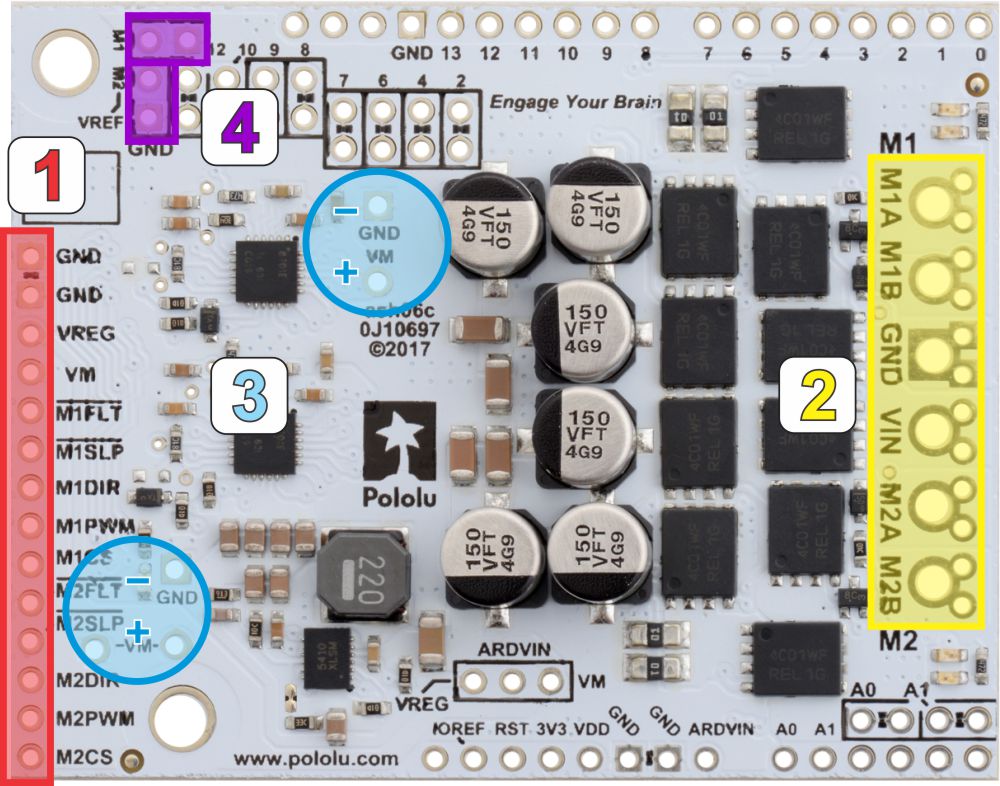 |
- Logic connections: The 14 small holes along the left side of the board, highlighted in red in the above diagram, are used to interface with the motor drivers. You can optionally solder a 1×14 piece of the included 0.1″ male header strip to these pins. Soldering the pins so they protrude down allows the logic side of the motor driver to be plugged into a standard solderless breadboard or perfboard, or they can be soldered facing up for use with custom cables. You can also solder 0.1″ female headers to these pins.
- Motor and power connections: The six large holes/twelve small holes on the right side of the board, highlighted in yellow in the above diagram, are the motor outputs and power inputs. You can optionally solder the included 5mm-pitch terminal blocks to the six large holes to enable temporary motor and motor power connections, or you can break off a 12×1 section of the included 0.1″ header strip and solder it into the smaller through-holes that border the six large motor and motor power pads. Note, however, that the terminal blocks are only rated for 16 A, and each header pin pair is only rated for a combined 6 A, so for higher-current applications, thick wires with high-current connectors should be soldered directly to the board. The smaller holes are intended only for 0.1″ header pins, not for the terminal blocks! Motor and power connections should not be made through a breadboard.
- Additional power capacitors: The motor driver includes six 100 µF or 150 µF electrolytic power capacitors, and the blue circles in the above picture show places where additional power capacitors can be added (e.g. to compensate for long power wires or increase stability of the power supply). Additional power capacitors are usually not necessary, and no additional capacitors are included with this motor driver.
- VREF: The default current limiting setting for the motor driver can be lowered by connecting a resistor between the VREF pins and the adjacent GND pins in the locations highlighted in purple in the above picture. For more details on adjusting the current limit threshold, see Section 4.b.


Home | Forum | Blog | Support | Ordering Information | Lists | Distributors | BIG Order Form | About | Contact
© 2001–2026 Pololu Corporation
