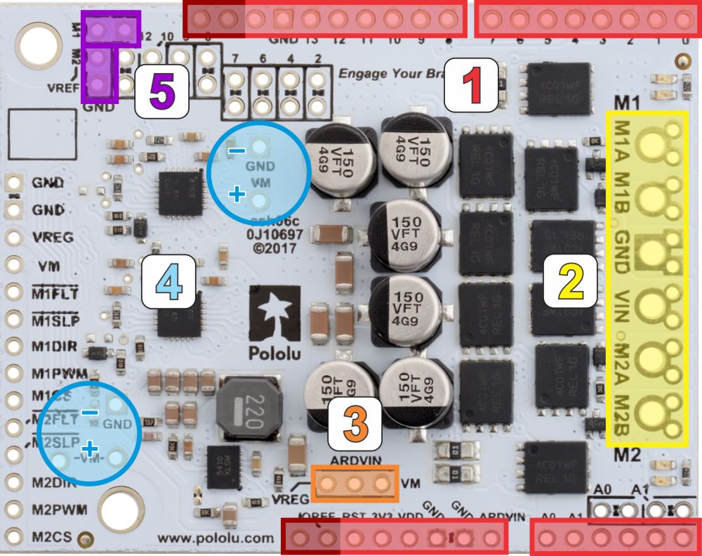
- Stackable Arduino headers: Before you can use this board as an Arduino shield, you need to solder four of the five included Arduino header strips to the set of holes highlighted in red in the picture above. The headers should be oriented so that the female sockets rest on the top side of the shield and face up while the male pins protrude down through the board, and the solder connections should be made on the underside of the shield. Newer Arduino boards, including the Uno R3 and the Leonardo, use one 1×10 header, two 1×8 headers, and one 1×6 header, as shown in the left picture below; older Arduino boards use two 1×8 headers and two 1×6 headers (the two pairs of pins highlighted in darker red should not be populated if you are using this board with an older Arduino that does not support these additional pins). Please make sure you solder the appropriate headers for your particular Arduino!
- Motor and power connections: The six large holes/twelve small holes on the right side of the board, highlighted in yellow in the above diagram, are the motor outputs and power inputs. You can optionally solder the included 5mm-pitch terminal blocks to the six large holes to enable temporary motor and motor power connections, or you can break off a 1×12 section of the included 0.1″ header strip and solder it into the smaller through-holes that border the six large motor and motor power pads. Note, however, that the terminal blocks are only rated for 16 A, and each header pin pair is only rated for a combined 6 A, so for higher-current applications, thick wires with high-current connectors should be soldered directly to the board. The smaller holes are intended only for 0.1″ header pins, not for the terminal blocks! Motor and power connections should not be made through a breadboard.
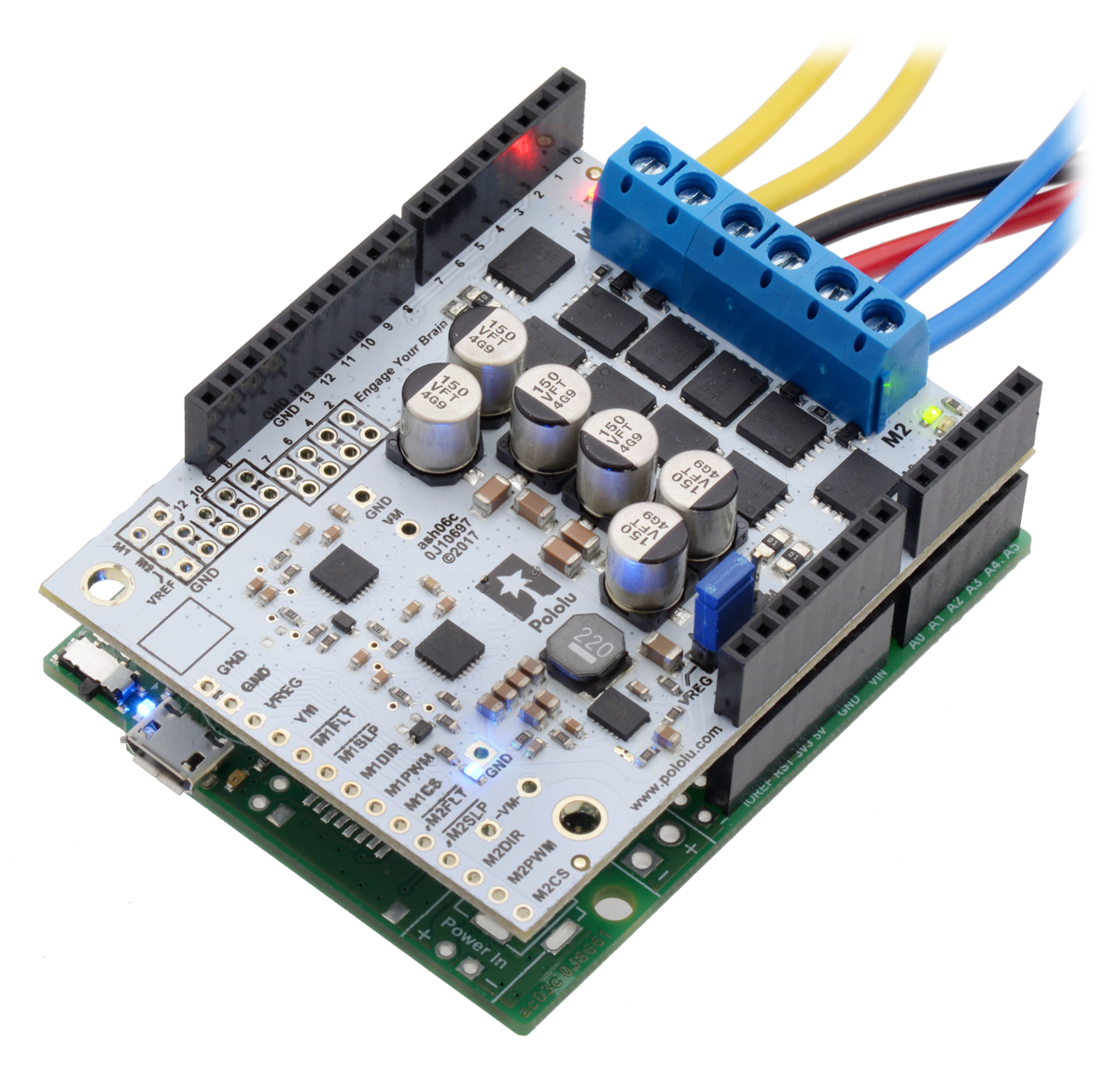
 | Pololu Dual G2 High-Power Motor Driver Shield being controlled by an A-Star 32U4 Prime. |
|---|
|
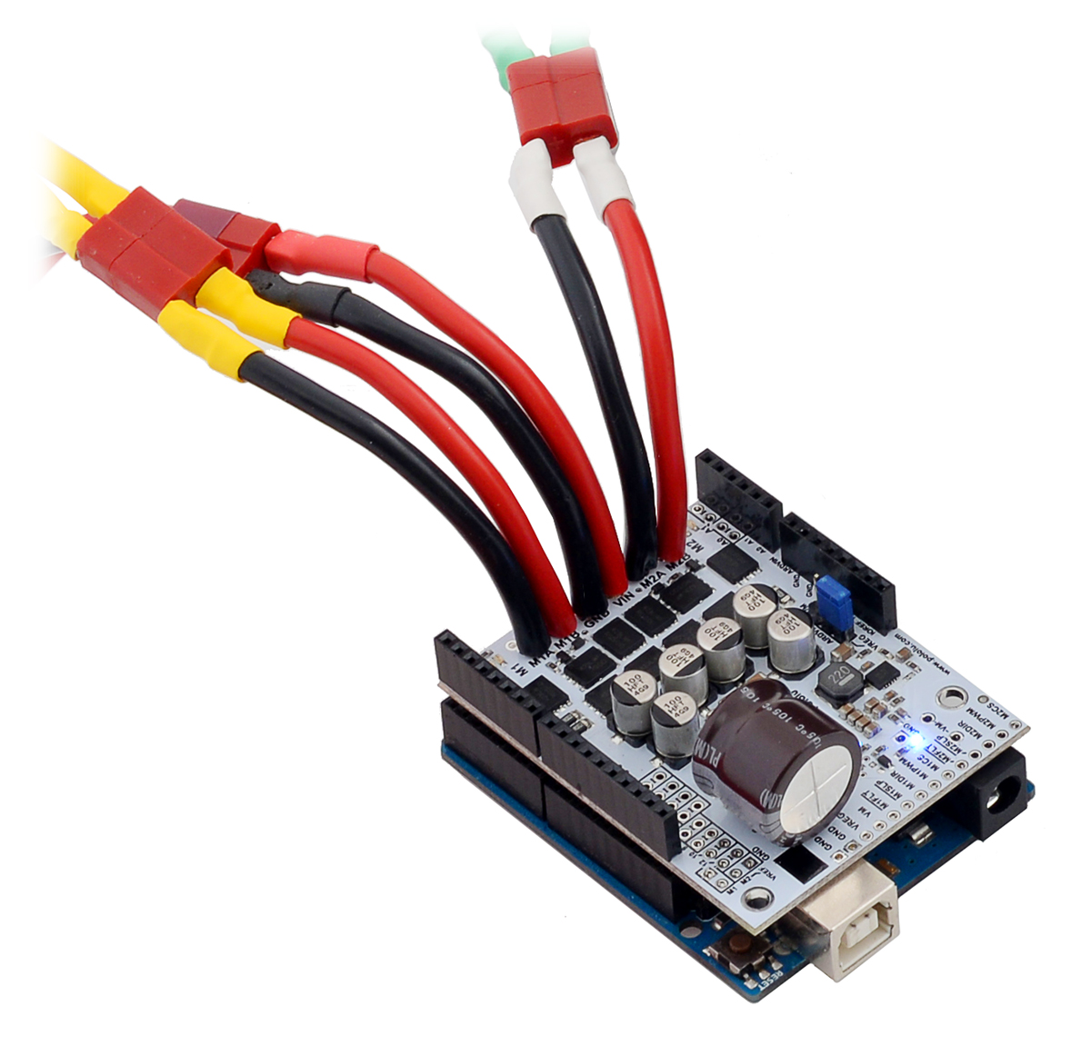
 | For high-current installations, motor and power supply wires should be soldered directly to the driver (the supplied terminal blocks are only rated for up to 16 A). |
|---|
|
- Arduino power jumper: If you want the option of using a single power supply for your entire system (rather than powering the shield and Arduino separately), you can solder a 1×3 piece of the included 0.1″ male header strip to the pins highlighted in orange in the above picture. The middle pin connects to the Arduino’s VIN pin, and you can use the included shorting block to supply this pin with either VM (reverse-protected shield VIN) or VREG (7.5 V by default when the shield VIN is over ~8 V) to power the Arduino. The shield can accept voltages that are well above what typical Arduinos can tolerate, so we strongly recommend putting the shorting block in the VREG position for power supplies over 9 V.
You should not use this feature to power the shield from the Arduino as this connection is not designed to handle high currents, and you must never supply power to the Arduino’s VIN pin or power jack while this shorting block is in place, because it will create a short between the shield power supply and the Arduino power supply and will likely permanently damage something.
- Additional power capacitors: The motor driver includes six 100 µF or 150 µF electrolytic power capacitors, and the blue circles in the above picture show places where additional power capacitors can be added (e.g. to compensate for long power wires or increase stability of the power supply). Additional power capacitors are usually not necessary, and no additional capacitors are included with this motor driver.
- VREF: The default current limiting setting for the motor driver can be lowered by connecting a resistor between the VREF pins and the adjacent GND pins in the locations highlighted in purple in the above picture. For more details on adjusting the current limit threshold, see Section 4.b.
The other through-holes on the shield are used for more advanced things like customizing the Arduino pin mappings and are not necessary for getting started using this shield with an Arduino. They are discussed in more detail later in this guide.