Support » Pololu Romi 32U4 Control Board User’s Guide » 3. Romi 32U4 Control Board »
3.3. Motor drivers and encoders
Motor drivers
The Romi 32U4 Control Board has two Texas Instruments DRV8838 motor drivers that are used to power the Romi chassis’s two mini plastic gearmotors. Four Arduino pins are used to control the drivers:
- Digital pin 15, or PB1, controls the right motor direction (LOW drives the motor forward, HIGH drives it in reverse).
- Digital pin 16, or PB2, controls the left motor direction.
- Digital pin 9, or PB5, controls the right motor speed with PWM (pulse width modulation) generated by the ATmega32U4’s Timer1.
- Digital pin 10, or PB6, controls the left motor speed with PWM.
For more information about the drivers, see the DRV8838 datasheet (1k redirect). We also sell a carrier board for this driver.
The Romi32U4 library provides functions that allow you to easily control the motors (see Section 6).
The motor driver connections are brought out to two pairs of headers that are intended to interface with the Romi Encoder Pair Kit. A pair of low-profile female headers is included with the Romi 32U4 Control Board and can be soldered into either the outer or inner row of through-holes on each side. (Note that these headers must be soldered into the positions that match the male header installed on the encoder board.)
As your batteries run out, the voltage supplied to the motor drivers (VSW) will decrease, which will make the motors slower. It is possible to account for this in your code by monitoring the battery voltage (see Section 3.5) or using the encoders and other sensors to monitor the movement of the robot.
Quadrature encoders
The Romi 32U4 Control Board is configured to connect the quadrature encoder outputs from the Romi Encoder Pair Kit to the ATmega32U4 microcontroller. The encoders can be used to track the rotational speed and direction of the robot’s drive wheels. They provide a resolution of 12 counts per revolution of the motor shaft when counting both edges of both channels, which corresponds to approximately 1440 counts per revolution of the Romi’s wheels. For more information about the specifications of the Romi encoders, please see the Romi Encoder Pair Kit product page.
Quadrature encoder transitions are often detected by monitoring both encoder channels directly. However, since transitions on the Romi’s encoders can occur at high frequencies (several thousand per second) when its motors are running, it is necessary to use the AVR’s pin change interrupts or external interrupts to read the encoders. To reduce the required number of interrupt pins, the Romi 32U4 Control Board XORs together both channels of each encoder and connects the resulting signal to an interrupt pin, while channel B of each encoder is connected to a non-interrupt pin:
- Digital pin 7, or PE6, reads the right encoder XORed signal using external interrupt INT6.
- Digital pin 8, or PB4, reads the left encoder XORed signal using pin change interrupt PCINT4.
- Digital pin 23 (analog pin 5), or PF0, reads the right encoder channel B.
- Pin PE2 reads the left encoder channel B.
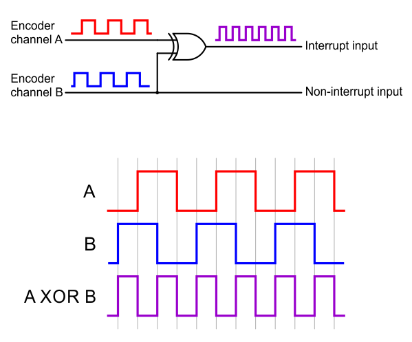 |
The XORed signal and the channel B signal can be used to reconstruct the channel A signal by simply XORing them again: (A XOR B) XOR B = A. For both encoders, channel B leads channel A when the motor is rotating in the forward direction; that is, B rises before A rises and B falls before A falls. (The waveforms in the diagram above would be produced by forward rotation.) Note that this description designates the A and B signals as labeled on the control board itself, which puts A in front on both sides.
The Romi32U4 library provides appropriate interrupt service routines and functions for reading the encoders and keeping track of their counts (see Section 6).
Related products


Home | Forum | Blog | Support | Ordering Information | Lists | Distributors | BIG Order Form | About | Contact
© 2001–2026 Pololu Corporation
