Support » Pololu A-Star 32U4 User’s Guide » 4. A-Star 32U4 Mini »
4.1. A-Star 32U4 Mini pinout and components
Pinout
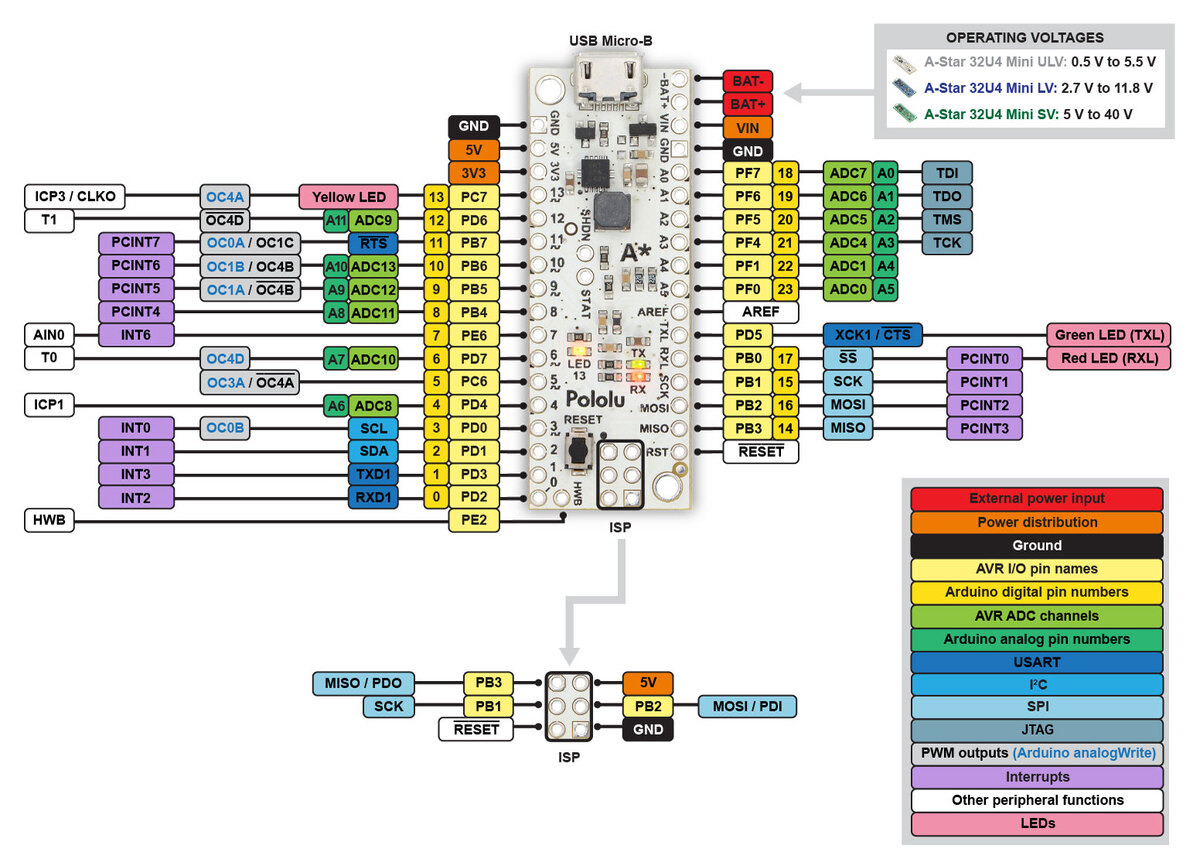 |
This diagram identifies the I/O and power pins on the A-Star 32U4 Mini (ULV, LV, and SV versions); it is also available as a printable PDF (223k pdf). For more information about the ATmega32U4 microcontroller and its peripherals, see Atmel’s ATmega32U4 documentation.
Printed on the A* circuit board are indicators that you can use to quickly identify each pin’s capabilities: a triangle next to the pin means it can be used as an analog input, and a square wave symbol under the pin number means it can be used as a PWM output.
LEDs
The A-Star 32U4 Mini has three indicator LEDs.
The yellow LED is connected to Arduino pin 13, or PC7. You can drive this pin high in a user program to turn this LED on. The A-Star 32U4 Bootloader fades this LED on and off while it is waiting for a sketch to be loaded.
The green LED is connected to the pin labeled TXL, or PD5, and lights when the pin is driven low. While the board is running the A-Star 32U4 Bootloader or a program compiled in the Arduino environment, it will flash this LED when it is transmitting data via the USB connection.
The red LED is connected to the pin labeled RXL (usable as Arduino pin 17), or PB0, and lights when the pin is driven low. While the board is running the A-Star 32U4 Bootloader or a program compiled in the Arduino environment, it will flash this LED when it is receiving data via the USB connection.
Connectors
The A-Star 32U4 includes a USB Micro-B connector that can be used to connect to a computer’s USB port via a USB A to Micro-B cable (not included). The USB connection can be used to transmit and receive data from the computer, and a preloaded USB bootloader makes it possible to program the board over USB. The USB connection can also provide power to the A-Star.
The board also has a 6-pin ISP header that allows it to be programmed with an external programmer, such as our USB AVR programmer v2.1. Pin 1 of the header is indicated with a small dot and has an octagonal shape.
Power
The A-Star 32U4 Mini can either be powered directly from the USB 5 V supply or from an external voltage source, which is regulated to 5 V by its onboard switching regulator.
The board’s power selection circuit uses the TPS2113A power multiplexer from Texas Instruments to choose whether its 5 V supply is sourced from USB or an external supply via the regulator, allowing both sources to be connected at the same time and enabling the A-Star to safely and seamlessly transition between them. The TPS2113A is configured to select external power unless the regulator output falls below about 4.5 V. If this happens, it will select the higher of the two sources, which will typically be the USB 5 V bus voltage if the A* is connected to USB. The currently selected source is indicated by the STAT pin in the middle of the board; this pin is an open-drain output that is low if the external power source is selected and high-impedance if the USB supply is selected. The current limit of the TPS2113A is set to about 1.9 A. For more information about the power multiplexer, see the TPS2113A datasheet (1k redirect).
In some situations, it might be undesirable for the A-Star 32U4 Mini to draw power from an external source when it is connected to USB. If this is the case, the regulator can be disabled by driving the regulator shutdown pin, SHDN, high; this shuts down the regulator and causes the power mux to fall back to USB power. For example, this could allow a battery-powered device to turn off the regulator and avoid draining its battery while it is connected to a computer.
The input voltage range of the regulator depends on the particular version of the A-Star 32U4 Mini:
- ULV: 0.5 V to 5.5 V (see Section 4.2 for regulator details)
- LV: 2.7 V to 11.8 V (see Section 4.3 for regulator details)
- SV (see Section 4.4 for regulator details):
- original ac02c version: 5 V to 36 V
- newer ac02f version: 5 V to 40 V
Reverse-protected power inputs: The BAT+ and BAT- pins are power inputs with reverse-voltage protection. These are the recommended pins to use when connecting an external power supply because they allow the A-Star’s reverse-voltage protection circuit to help prevent it from being damaged by accidentally-reversed power connections.
VIN power output (or alternative input): When power is supplied through the BAT pins, the VIN pin can be used as an output to supply reverse-protected power to other devices. Alternatively, the external supply can be connected directly between VIN and GND, bypassing the reverse-voltage protection.
5V power output: This pin provides access to the board’s 5 V supply, which comes from either the USB 5 V bus voltage or the onboard switching regulator, depending on which power sources are connected and enabled. Note that some of the available current on the 5 V line is used by the board itself (typically about 30 mA) or used to provide current for the GPIO pins or 3.3 V power output (see below).
3V3 power output: This pin gives access to the output of the internal 3.3 V regulator inside the ATmega32U4. The microcontroller uses this regulated voltage for USB signaling, but up to about 50 mA is available for powering external circuits or devices.
When the A-Star 32U4 Mini is being powered through VIN, the sum of the 5V output current, 3V3 output current, GPIO output current, and current used by the board itself should not exceed the maximum current that the regulator can provide; see the following sections for details about the regulator on each version.
Related products


Home | Forum | Blog | Support | Ordering Information | Lists | Distributors | BIG Order Form | About | Contact
© 2001–2026 Pololu Corporation
