Support »
Pololu RC Switch User’s Guide
View document on multiple pages.
- 1. Overview
- 2. RC Switch with Digital Output
- 3. RC Switch with Small Low-Side MOSFET
- 4. RC Switch with Medium Low-Side MOSFET
- 5. RC Switch with Isolated Solid State Relay/Switch
- 6. RC Switch with Relay
- 7. Pololu 4-Channel RC Servo Multiplexer
- 8. Functional Description
- 9. Outputs and Indicator LED
- 10. Configuring Your RC Switch
1. Overview
 |
The Pololu RC switches allow you to turn devices on and off using standard radio control (RC) pulses. These switches can be used with standard hobby RC systems for radio-controlled switch applications. Example applications include using extra channels on an RC receiver or servo controller to turn on lights, motors, or irrigation valves.
The RC switch measures the width of incoming RC pulses and compares it to a user-configurable threshold (with ±64 µs of hysteresis) to decide whether to activate the switch. By default, the threshold is approximately 1700 μs, with switch activation occurring above the threshold (longer pulses), but the switch has a learning mode that allows you to change the threshold and the activation direction. A safe-start feature reduces the likelihood of unexpected activation on all RC switches except the RC Servo Multiplexer.
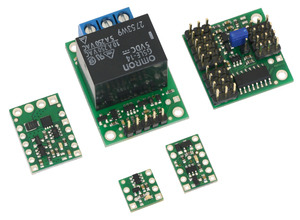
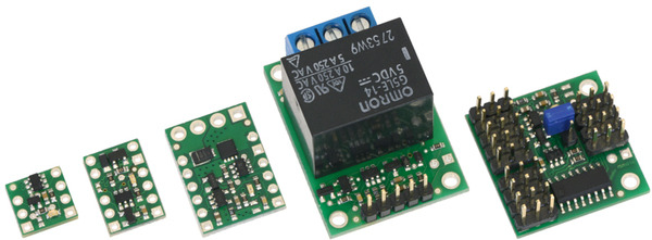
The RC Switch family
|
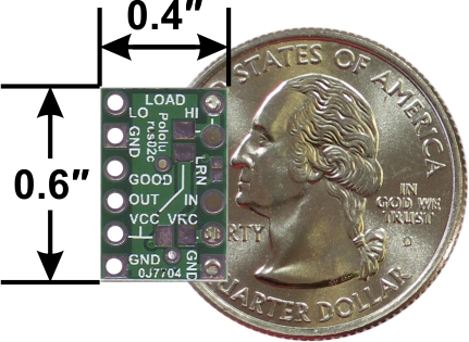
The Pololu RC Switch with Digital Output is the most basic RC switch. This extremely compact (0.4″ × 0.4″) board can fit on a U.S. dime and has two digital outputs that indicate whether the switch is active and whether the input signal is valid. (These outputs are also available on all the other RC switches.) |

|
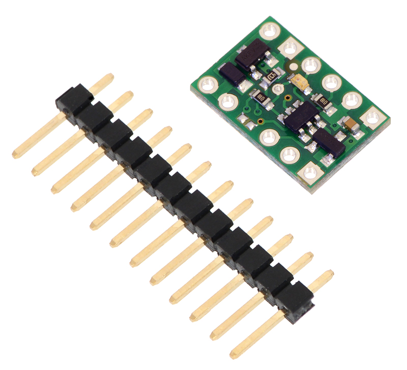
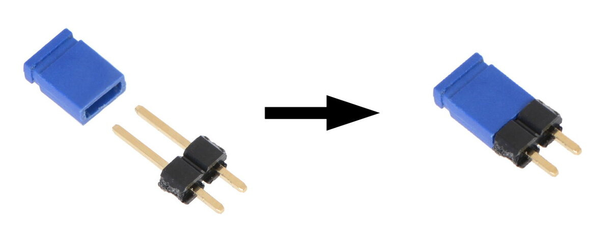
The Pololu RC Switch with Small Low-Side MOSFET has an integrated low-side MOSFET that allows it to drive small loads (up to around 3 A). It ships with male header pins included but not soldered in. |

|
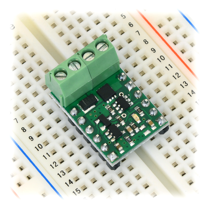
The Pololu RC Switch with Medium Low-Side MOSFET has an integrated low-side MOSFET that allows it to drive moderate loads (up to around 15 A) and a voltage regulator that allows more options for powering the board. The included screw terminal block makes it easy to connect the load and load supply wires directly to the board. This RC switch ships with a 1×4 terminal block and male header pins included but not soldered in. |

|
The Pololu RC Switch with Isolated Solid State Relay/Switch features a single-pole, single-throw (SPST) solid state relay, allowing it to drive bidirectional, electrically isolated loads with currents up to around 10 A. These boards also have an integrated voltage regulator. Two versions are available with different load voltage and current capabilities, and each of those is available with connectors soldered or without connectors. |

|
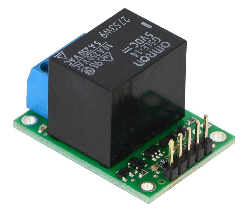
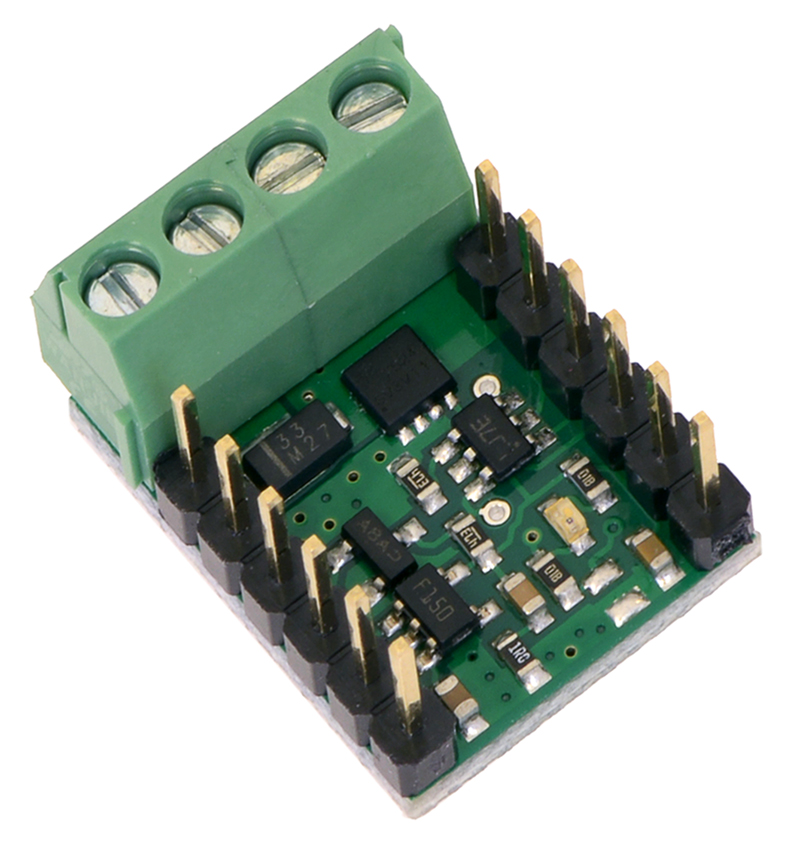
The Pololu RC Switch with Relay features a single-pole, double-throw (SPDT) relay, allowing it to drive large, electrically isolated loads. This board also has an integrated voltage regulator. It is available fully assembled or as a partial kit. Please note that relays make a clicking sound when they are turned on or off, so the RC Switch with Relay might not be suitable for applications requiring quiet operation. |

|
The Pololu 4-Channel RC Servo Multiplexer is an RC switch with an integrated quad 2-input multiplexer and a voltage regulator. It allows easy switching of servo control between two independent sources. It is ideal for applications in which you have two possible control sources and want to be able to switch between them on the fly. The RC multiplexer is available fully assembled or as a partial kit. |

In this guide, we use the term “RC switch” to refer to all members of the Pololu RC Switch family, including the RC multiplexer.
|
|
Note: This guide does not apply to our older RC switches (products #721, #722, #752, #1210, #1211).
1.1. Contacting Pololu
 |
We would be delighted to hear from you about any of your projects and about your experience with the RC switch. You can contact us directly or post on our forum. Tell us what we did well, what we could improve, what you would like to see in the future, or anything else you would like to say!
2. RC Switch with Digital Output
2.1. Pinout
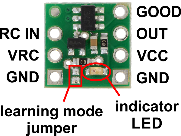 |
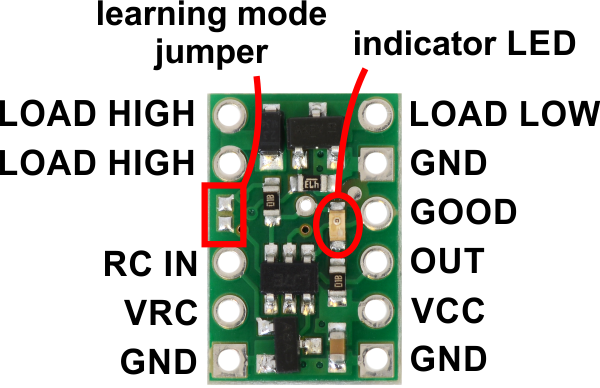
Pololu RC Switch with Digital Output, labeled top view. |
|---|
The Pololu RC Switch with Digital Output has 7 through holes spaced 0.1″ apart that fit 0.1″ header pins.
RC interface
The GND, VRC, and RC IN pins make up the switch’s RC interface and can be connected directly to an RC receiver or servo controller:
- The GND pin is the ground or reference voltage.
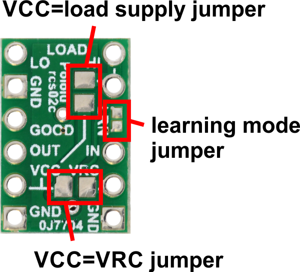
- The VRC pin connects to the RC power line. The power from VRC is not used by default, but a jumper on the bottom of the board can be bridged with solder to power the board from VRC.
- The RC IN pin is the RC signal input. The switch measures the width of pulses on this line and uses that to decide whether to activate or not.
Power
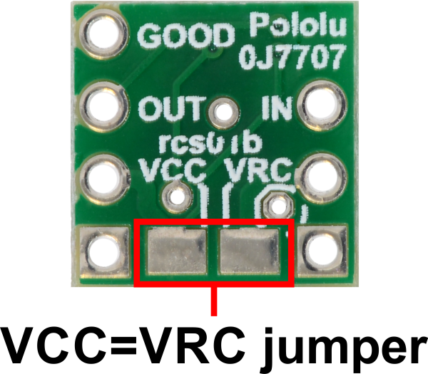 |
The VCC pin powers the basic functions of the board and needs to be connected to a power source between 2.5 V and 5.5 V. The VCC=VRC jumper on the bottom of the board can be bridged with solder to power the board from VRC or to pass power from VCC to the RC receiver.
Outputs and indicator LED
The RC switch provides feedback about what state it is in via a yellow indicator LED. The LED behavior is described in Section 9. Status information is also provided by two outputs:
- The GOOD pin indicates the presence of a valid RC signal (10–330 Hz pulse rate, 0.5–2.5 ms pulse width).
- The OUT pin indicates whether the switch is active.
When these outputs are high they will be at the same voltage level as VCC. When low, these outputs will be at 0 V (ground). These outputs do not have resistors in series with them. Each output can source or sink up to 25 mA.
Configuration interface
The learning mode jumper on the top of the board can be used to get the device into learning mode and configure it. The configuration procedure is described in Section 10.
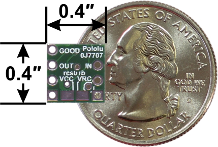 |
Pololu RC Switch with Digital Output, bottom view with dimensions. |
|---|
Included hardware
A 7-pin 0.1″ straight breakaway male header is included with the Pololu RC Switch with Digital Output. The header pins can be soldered in and used to connect the RC switch to perfboards or breadboards.
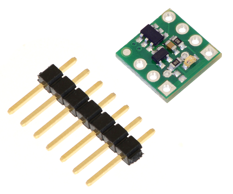 |
Pololu RC Switch with Digital Output with included hardware. |
|---|
2.2. Wiring Diagram
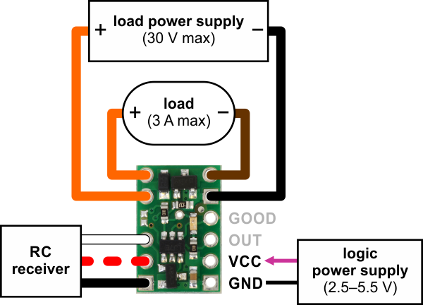
The typical way to connect the Pololu RC Switch with Digital Output is shown in the diagram below:
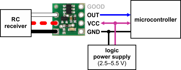 |
Typical wiring diagram for the Pololu RC Switch with Digital Output. |
|---|
The RC switch can be plugged directly into an RC receiver or servo controller using a Female-Female servo extension cable. These can be found in our Servo Cables category. The switch will read the signal from the RC receiver, but in the default configuration it will not draw or supply any power to the receiver, so the power wire is optional. The receiver will need its own power source.
Power for the switch’s logic needs to be applied to GND and VCC and must be between 2.5 V and 5.5 V. Many microcontroller boards have a 3.3 V or 5 V line that powers the microcontroller and would also be suitable for powering the RC switch.
The OUT line can be connected to a digital input pin on the microcontroller.
Power jumper
The setup described above involves two separate power supplies. For some applications, this setup can be simplified by bridging the VCC=VRC power jumper on the bottom of the board. This allows you to either power the microcontroller and RC switch from the RC receiver’s power supply or to power the RC receiver and RC switch from the microcontroller’s power supply.
|
2.3. Schematic Diagram
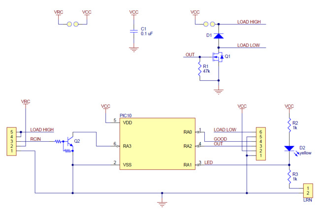
The schematic diagram of the Pololu RC Switch with Digital Output is shown below:
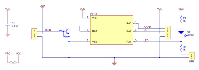 |
This schematic is also available as a printable pdf (126k PDF).
3. RC Switch with Small Low-Side MOSFET
3.1. Pinout
 |
Pololu RC Switch with Small Low-Side MOSFET, top labeled view. |
|---|
The Pololu RC Switch with Small Low-Side MOSFET has 11 through holes spaced 0.1″ apart that fit 0.1″ header pins.
RC interface
The GND, VRC, and RC IN pins make up the switch’s RC interface and can be connected directly to an RC receiver or servo controller:
- The GND pin is the ground or reference voltage.
- The VRC pin connects to the RC power line. The power from VRC is not used by default, but a jumper on the bottom of the board can be bridged with solder to power the board from VRC as described below.
- The RC IN pin is the RC signal input. The switch measures the width of pulses on this line and uses that to decide whether to activate or not.
Power
 |
This board involves three potentially-different power supplies:
- VCC: The VCC pin powers the basic functions of the board and needs to be connected to a power source between 2.5 V and 5.5 V. VCC is also the gate voltage that is used to turn the MOSFET on, so it should be noted that lower VCC voltages will lead to higher MOSFET on resistances, which in turn limits the maximum current the device can switch.
- VRC: The VRC pin will generally be connected the power line from your RC system. By default, power from this pin is not used by the board, so this pin is optional.
- LOAD HIGH: The two pins labeled LOAD HIGH will generally be connected to the positive terminal of the load power supply and to the positive terminal of the load.
The bottom of the board has jumpers that can be bridged with solder in order connect VCC to VRC or VCC to LOAD HIGH. These jumpers provide extra flexibility in how the system is powered, and some examples are given in Section 3.2.
Load interface
The LOAD LOW and LOAD HIGH pins are connections for your load and load supply. The LOAD LOW pins are normally disconnected from GND, but when the switch activates the MOSFET turns on and connects LOAD LOW to GND. There is a flyback (also known as a “freewheeling”) diode between LOAD LOW and LOAD HIGH. The board’s MOSFET can deliver up to 3 A with VCC at 5 V and can handle load supply voltages up to 30 V. More details on connecting your load and load supply to the switch can be found in Section 3.2.
Outputs and indicator LED
The RC switch provides feedback about what state it is in via a yellow indicator LED. The LED behavior is described in Section 9. Status information is also provided by two additional outputs:
- The GOOD pin indicates the presence of a valid RC signal (10–330 Hz pulse rate, 0.5–2.5 ms pulse width).
- The OUT pin indicates whether the MOSFET is on.
When these outputs are high they will be at the same voltage level as VCC. When low, these outputs will be at 0 V (ground). These outputs do not have resistors in series with them. Each output can source or sink up to 25 mA.
Configuration interface
The learning mode jumper on both the top and bottom of the board can be used to get the device into learning mode and configure it. The configuration procedure is described in Section 10.
 |
Pololu RC Switch with Small Low-Side MOSFET, bottom view with dimensions. |
|---|
Included hardware
A 12-pin 0.1″ straight breakaway male header is included with the Pololu RC Switch with Small Low-Side MOSFET. The header pins can be soldered in and used to connect the RC switch to perfboards or breadboards.
 |
Pololu RC Switch with Small Low-Side MOSFET with included hardware. |
|---|
3.2. Wiring Diagram
The typical way to connect the Pololu RC Switch with Small Low-Side MOSFET is shown in the diagram below:
 |
Pololu RC Switch with Small Low-Side MOSFET, typical wiring diagram. |
|---|
The RC switch can be plugged directly into an RC receiver or servo controller using a Female-Female servo extension cable. These can be found in our Servo Cables category. The switch will read the signal from the RC receiver, but in the default configuration it will not draw or supply any power to the receiver, so the power wire is optional. The receiver will need its own power source.
Power for the board’s logic needs to be applied to GND and VCC and must be between 2.5 V and 5.5 V. A 5 V regulator would be a good choice for the logic power supply. A 3-cell NiMH battery pack would also work, but a 4-cell NiMH battery pack can be well over 5.5 V when fully charged and would not be suitable.
The negative side of your load supply should connect to the GND pad on the top-right side of the board, and the negative side of the load itself should connect to the LOAD LOW pin. The two pins labeled LOAD HIGH are internally connected and will typically be connected to both the load and the load power supply. There is a flyback (also known as a “freewheeling”) diode between the MOSFET output and LOAD HIGH, which allows you to safely connect an inductive load such as a motor or relay. Alternatively, the positive side of the load could be directly connected to the load supply off of the board. The board’s MOSFET can deliver up to 3 A with VCC at 5 V and can handle load supply voltages up to 30 V.
Power jumpers
The setup described above involves three separate power supplies. For some applications, this setup can be simplified by bridging one or both of the power jumpers on the bottom of the board.
|
Here are some alternative options for powering your system with fewer than three power supplies:
- If the VRC supply from the RC receiver is between 2.5 V and 5.5 V, then you could bridge the VCC=VRC jumper in order to power the board from VRC and avoid the need for a separate logic power supply connected to VCC. Alternatively, supplying power to VCC and bridging VCC=VRC could allow you to power your RC receiver from the RC switch.
- If your load supply is between 2.5 V and 5.5 V, then you could bridge the VCC=load supply jumper, allowing you to power the board from either the LOAD HIGH or VCC pin.
- With both jumpers bridged, the whole system can be powered from a single suitable source.
Large or capacitive loads can cause problems if the same supply is used for the logic (VCC) and the load. In such a configuration, when the MOSFET turns on, VCC might drop below 2.5 V, causing the board to reset. If you try to activate the switch but the board just goes into safe-start mode instead, you might have a power issue, especially if the problem only happens when the load is connected. If you have this problem, you should consider using a separate logic power supply, adding a capacitor between GND and VCC, or using shorter power leads.
3.3. Schematic Diagram
The schematic diagram of the Pololu RC Switch with Small Low-Side MOSFET is shown below:
 |
This schematic is also available as a printable pdf (143k PDF).
4. RC Switch with Medium Low-Side MOSFET
4.1. Pinout
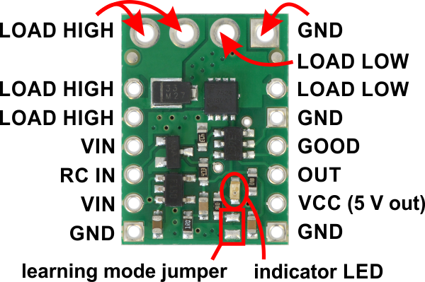 |
Pololu RC Switch with Medium Low-Side MOSFET, labeled top view. |
|---|
The Pololu RC Switch with Medium Low-Side MOSFET has 12 smaller through holes spaced 0.1″ apart that fit 0.1″ header pins and four larger holes that fit 3.5 mm screw terminals.
RC interface
The GND, VIN, and RC IN pins make up the switch’s RC interface and can be connected directly to an RC receiver or servo controller:
- The GND pin is the ground or reference voltage.
- The VIN pin is the power input.
- The RC IN pin is the RC signal input. The switch measures the width of pulses on this line and uses that to decide whether to activate or not.
Power
The VIN pins power the basic functions of the board and need to be connected to a power source between 2.5 V to 16 V. This allows the board to be powered from a 4- or 5-cell NiMH or NiCD battery pack through an RC receiver or separately.
The VCC pin connects to the output of the onboard regulator and is 5 V when the board is powered with a source that is greater than or equal to 5 V and approximately equal to VIN when it is below 5 V. VCC is also the gate voltage that is used to turn the MOSFET on, so it should be noted that lower VCC voltages will lead to higher MOSFET on resistances, which in turn limits the maximum current the device can switch.
Load interface
The LOAD LOW and LOAD HIGH pins are connections for your load and load supply. The LOAD LOW pins are normally disconnected from GND, but when the switch activates the MOSFET turns on and connects LOAD LOW to GND. There is a flyback (also known as a “freewheeling”) diode between LOAD LOW and LOAD HIGH. The board’s MOSFET can deliver up to 15 A with VCC at 5 V and can handle load supply voltages up to 30 V. More details on connecting your load and load supply to the switch can be found in Section 4.2.
Outputs and indicator LED
The RC switch provides feedback about what state it is in via a yellow indicator LED. The LED behavior is described in Section 9. Status information is also provided by two additional outputs:
- The GOOD pin indicates the presence of a valid RC signal (10–330 Hz pulse rate, 0.5–2.5 ms pulse width).
- The OUT pin indicates whether the MOSFET is on.
When these outputs are high they will be at the same voltage level as VCC. When low, these outputs will be at 0 V (ground). These outputs do not have resistors in series with them. Each output can source or sink up to 25 mA.
Configuration interface
The learning mode jumper on both the top and bottom of the board can be used to get the device into learning mode and configure it. The configuration procedure is described in Section 10.
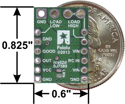 |
Pololu RC Switch with Medium Low-Side MOSFET, bottom view with dimensions. |
|---|
Included hardware
A 12-pin 0.1″ straight breakaway male header and two 3.5 mm 2-pin terminal blocks are included with the Pololu RC Switch with Medium Low-Side MOSFET. The header pins can be soldered in and used to connect the RC switch to perfboards or breadboards. Please note that the included terminal blocks are only rated for 10 A; for higher power applications, use thick wires soldered directly to the board.
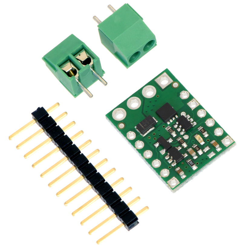 |
Pololu RC Switch with Medium Low-Side MOSFET with included hardware. |
|---|
4.2. Wiring Diagram
The typical way to connect the Pololu RC Switch with Medium Low-Side MOSFET is shown in the diagram below:
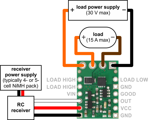 |
Typical wiring diagram for the Pololu RC Switch with Medium Low-Side MOSFET. |
|---|
An onboard regulator allows the switch to be powered from voltages between 2.5 V and 16 V. However, for most applications we recommend using a 4- or 5-cell NiMH or NiCD battery pack to power the switch. The battery pack will typically be connected to an RC receiver or servo controller, which passes the power on to the RC switch. The switch can be plugged directly into the RC receiver using a Female-Female servo extension cable. These can be found in our Servo Cables category.
The negative side of your load supply should connect to the GND pad on the top-right side of the board, and the negative side of the load itself should connect to the LOAD LOW pin. The four pins labeled LOAD HIGH are internally connected and intended to give you convenient connection points for both your load and your load power supply. There is a flyback (also known as a “freewheeling”) diode between the MOSFET output and LOAD HIGH, which allows you to safely connect an inductive load such as a motor or relay. Alternatively, the positive side of the load could be directly connected to the load supply off of the board. The board’s MOSFET can deliver up to 15 A with VCC at 5 V and can handle load supply voltages up to 30 V.
For lower power applications the smaller 0.1″-spaced pins can be used instead of the terminal block to connect the load and load supply.
|
|
4.3. Schematic Diagram
The schematic diagram of the Pololu RC Switch with Medium Low-Side MOSFET is shown below:
 |
This schematic is also available as a printable pdf (156k pdf).
5. RC Switch with Isolated Solid State Relay/Switch
5.1. Pinout
|
|

The Pololu RC Switch with Isolated Solid State Relay/Switch has five pins spaced 0.1″ apart that give access to its logic interface.
RC interface
The GND, VRC, and RC IN pins make up the switch’s RC interface and can be connected directly to an RC receiver or servo controller:
- The GND pin is the ground or reference voltage.
- The VRC pin is the power input.
- The RC IN pin is the RC signal input. The switch measures the width of pulses on this line and uses that to decide whether to activate or not.
Power
The VRC pin powers the basic functions of the board and needs to be connected to a power source between 2.7 V to 16 V. This allows the board to be powered from a 4- or 5-cell NiMH or NiCD battery pack through an RC receiver or separately. The board’s control circuit will typically draw up to 15 mA from VRC when the switch is enabled and up to 5 mA when the switch is closed.
The logic is powered by an on-board regulator that outputs 5V when VRC is above 5 V. When VRC is below 5 V, the board’s logic level is approximately equal to VRC.
Load interface
The two slots on the opposite side of the board from the logic interface provide access to the switch. The switching is performed by a pair of MOSFETs controlled by an optically isolated driver that galvanically isolates the load from the control inputs. The MOSFETs are arranged back-to-back to make the two outputs symmetric and equivalent, allowing bidirectional current control with the switch in any orientation relative to the load (for example, this board can be used for high-side or low-side switching). Benefits over modules with mechanical relays with comparable current ratings include silent operation, a smaller form factor, and immunity to problems like contact wear and arcing that limit the service life of mechanical relays.
Versions of this switch are available with different voltage and current capabilities, and each of those is available with connectors soldered or without connectors:
| Max load voltage | Max load current | Connectors | Item # |
|---|---|---|---|
| 60 V | 6 A | soldered | #5422 |
| not included | #5423 | ||
| 30 V | 10 A | soldered | #5424 |
| not included | #5425 |
Real-world power dissipation considerations
In our tests, we found that the 30 V version of the relay/switch could conduct about 10 A continuously, and the 60 V version could conduct about 6 A continuously, without reaching the thermal limit for the MOSFETs. Our tests were conducted at approximately 25°C ambient temperature with no forced air flow.
The actual current you can pass through the board will depend on how well you can keep it cool. The printed circuit board is designed to help with this by drawing heat out of the MOSFETs. Solid connections to the output pins (such as with thick soldered wires) can also help reduce heat build-up in the MOSFETs and board.
Warning: Exceeding temperature or current limits can cause permanent damage to the MOSFETs. If you are switching an average continuous current greater than about 2/3 of the specified maximum, we strongly recommend that you monitor the MOSFETs’ temperature and look into additional cooling if necessary.
This product can get hot enough to burn you long before the chip overheats. Take care when handling this product and other components connected to it.
Creepage and high voltage isolation considerations
This product is designed to be compact, without consideration for extra creepage that is often associated with solid state relays and electrically isolated systems. As such, this product is not suitable for isolating regions at significantly different voltages. For an alternative that can provide the same functionality with significantly higher isolation voltage ratings, consider using our RC Switch with Digital Output with our Isolated Solid State Relays.
Outputs and indicator LED
The RC switch provides feedback about what state it is in via a yellow indicator LED. The LED behavior is described in Section 9. Status information is also provided by two additional outputs:
- The GOOD pin indicates the presence of a valid RC signal (10–330 Hz pulse rate, 0.5–2.5 ms pulse width).
- The OUT pin indicates whether the relay is activated (i.e. the relay coil is energized).
When high, the GOOD and OUT outputs will output a voltage approximately equal to 5 V or VRC, whichever is lower. When low, these outputs will be at 0 V (ground). These outputs do not have resistors in series with them. Each output can source or sink up to 25 mA.
Configuration interface
The learning mode jumper can be used to get the device into learning mode and configure it. The configuration procedure is described in Section 10.
Assembly options
The Pololu RC Switch with Isolated Solid State Relay versions are available with connectors soldered or without connectors
- Connectors soldered versions ship as shown in the left picture below, with 1×3 0.1″ male headers soldered to the RC control inputs, and these headers are compatible with standard servo cables that can be used to connect it directly to an RC receiver or servo controller. The two load connection points are accessible via a soldered 2-pin, 3.5mm-pitch terminal block.
- Versions without included connectors give you the flexibility to choose different connections. The control pins work with 0.1″-pitch male headers and female headers and are compatible with standard solderless breadboards. The load side of the board has two 0.045″×0.095″ slots that can accommodate 3.5mm-pitch and 5mm-pitch terminal blocks, a 1×2 0.2″-pitch header, or a 1×3 0.1″-pitch male header with the middle pin removed. Wires can also be soldered directly to the slots for high-current applications.
|
|


5.2. Wiring Diagram
The typical way to connect the Pololu RC Switch with Isolated Solid State Relay is shown in the diagram below:
 |
Typical wiring diagram for the Pololu RC Switch with Isolated Solid State Relay/Switch, SPST. |
|---|
The switch is symmetrical and bidirectional, so it can be connected on the high side or low side and used with AC or DC supplies.
For inductive loads powered from a DC supply, a flyback diode (also called a freewheeling diode) can be connected across the load as shown below to reduce inductive voltage spikes when the switch turns off.
 |
Typical wiring diagram for the Pololu RC Switch with Isolated Solid State Relay/Switch, SPST when using a DC load supply with an inductive load. |
|---|
5.3. Schematic and Dimension Diagrams
The schematic diagram of the Pololu RC Switch with Isolated Solid State Relay is shown below:
 |
Schematic diagram of the Pololu RC Switch with Isolated Solid State Relay/Switch, SPST. |
|---|
The dimension diagram is available as a downloadable PDF (299k pdf).
6. RC Switch with Relay
6.1. Pinout
 |
Pololu RC Switch with Relay, labeled top view. |
|---|
The Pololu RC Switch with Relay has five pins spaced 0.1″ apart that give access to its logic interface.
RC interface
The GND, VRC, and RC IN pins make up the switch’s RC interface and can be connected directly to an RC receiver or servo controller:
- The GND pin is the ground or reference voltage.
- The VRC pin is the power input.
- The RC IN pin is the RC signal input. The switch measures the width of pulses on this line and uses that to decide whether to activate or not.
Power
We generally recommend that you supply the GND and VRC pins with power from a 4- or 5-cell NiMH or NiCD battery pack. Typically, the input voltage range will be limited by the properties of the relay coil. The included Omron G5LE-14-DC5 relay requires an input voltage of at least 3.75 V to operate. At room temperature (23° C), the relay can tolerate voltages up to 8.5 V, but this limit decreases at higher temperatures. At 85° C, the relay can only tolerate voltages up to 6.5 V. You can see the Omron G5LE-14-DC5 datasheet (1MB pdf) for more information. As a whole, the switch will draw about 100 mA when the relay is on, but that current draw depends on the input voltage. The board itself can operate anywhere in the 2.5 to 16 V range, but the included Omron relay requires a more restrictive range of voltages.
Relay interface
The NO, NC, and COM pins are connected directly to the relay.
- NO stands for “normally open”. This pin is normally disconnected from the COM pin, but they become connected when the relay is active.
- NC stands for “normally connected”. The NC pin is normally connected to the COM pin through the relay, but they become disconnected when the relay is active.
- COM stands for “common”.
These pins are electrically isolated from the logic side of the board and are routed on the PCB with a minimum clearance of 60 mils (1.5 mm) from other copper and from the board edges, though manufacturing variations in the board edges can make those distances slightly lower.
In most applications, the current and voltage ratings for the module will match the ratings of the relay used. Maximum current, maximum voltage, and life expectancy are interdependent; we therefore recommend careful examination of your relay’s datasheet. If you are using the included relay, please refer to the Omron G5LE-14-DC5 datasheet (1MB pdf) for information.
Warning: The RC Switch with Relay is not designed to or certified for any particular high-voltage safety standard. Working with voltages above 30 V can be extremely dangerous and should only be attempted by qualified individuals with appropriate equipment and protective gear.
Outputs and indicator LED
The RC switch provides feedback about what state it is in via a yellow indicator LED. The LED behavior is described in Section 9. Status information is also provided by two additional outputs:
- The GOOD pin indicates the presence of a valid RC signal (10–330 Hz pulse rate, 0.5–2.5 ms pulse width).
- The OUT pin indicates whether the relay is activated (i.e. the relay coil is energized).
When high, the GOOD and OUT outputs will output a voltage approximately equal to 5 V or VRC, whichever is lower. When low, these outputs will be at 0 V (ground). These outputs have 220 Ohm resistors in series with them to protect them from short circuits.
Configuration interface
The learning mode jumper can be used to get the device into learning mode and configure it. The configuration procedure is described in Section 10.
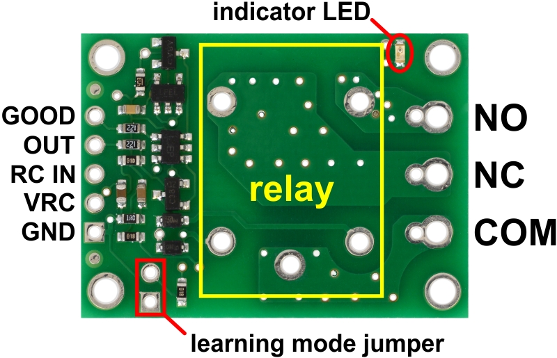 |
Pololu RC Switch with Relay carrier board, labeled top view. |
|---|
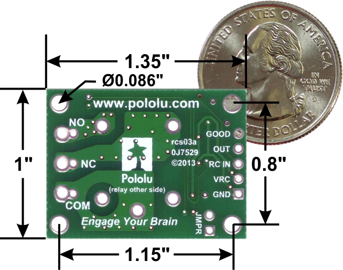 |
Pololu RC Switch with Relay, bottom view with dimensions. |
|---|
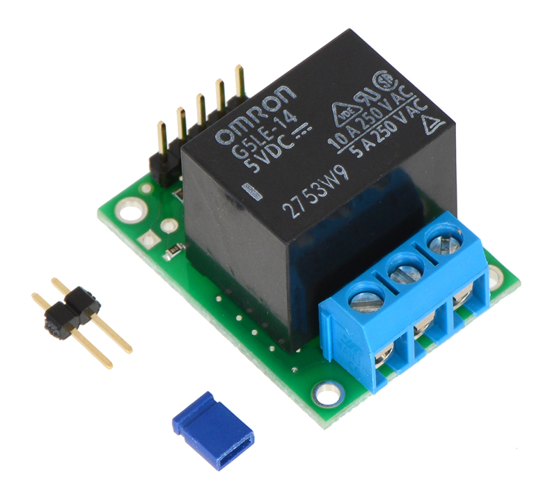
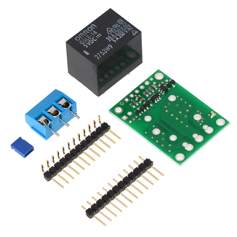
Included hardware
The Pololu RC Switch with Relay is available in two versions:
- The assembled version ships with the 5V Omron relay, header pins, and terminal block soldered in. A 1×2-pin male header and a shorting block are also included with the assembled version and can be used together as a tool when configuring the device. The assembled version can be incorporated into an existing RC system without the need for any additional soldering.
- The partial kit version gives you the flexibility to choose different connections. It includes a 5V Omron relay, 0.1″ 12-pin male header, a 0.1″ 12-pin right-angle male header, a 3-pin terminal block, and a shorting block. The headers can be broken into smaller pieces and optionally soldered to the board, or wires can be soldered directly to the board for the most compact installation.
Warning: When soldering the terminal block into the partial kit version, be sure to use the larger set of holes. If you use the smaller holes, which are intended for 0.2″ male header pins, there will not be enough space to mount the relay.
|
|
6.2. Wiring Diagram
The typical way to connect the Pololu RC Switch with Relay is shown in the diagram below:
 |
Typical wiring diagram for the Pololu RC Switch with Relay. |
|---|
We generally recommend that you use a 4- or 5-cell NiMH or NiCD battery pack for the logic power supply. The power supply will typically be connected to the RC receiver, which passes the power on to the RC switch. The switch can be plugged directly into the RC receiver using a Female-Female servo extension cable. These can be found in our Servo Cables category.
One typical way of connecting the relay is to put it between the load and the positive terminal of the load’s power supply. The load is the device that you want to control with the RC switch. The negative terminal of the power supply should connect to the other side of the load. The negative terminal of the power supply does not necessarily need to be connected to the GND pin of the logic side. In the diagram above, the positive terminal of the load power supply is connected to the NO pin and the positive terminal of the load is connected to COM. They will normally be disconnected, but when the switch turns on, the relay will activate and connect the two, allowing the load to be powered.
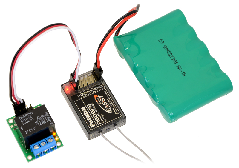 |
The Pololu RC Switch with Relay connected to a typical RC receiver. |
|---|
6.2. Connecting the 4-Channel RC Servo Multiplexer
The RC multiplexer pins are spaced 0.1″ apart so the servo inputs can be plugged directly into an RC receiver or servo controller using a Female-Female servo extension cable. These can be found in our Servo Cables category. The column of pins along the outside edge of the board is GND (ground) and the column in the middle is power.
We recommend that you connect the SEL and M1–M4 inputs to a single “master” RC device, such as an RC receiver or servo controller. The master device should have a power source that supplies power the RC multiplexer. The power supplied by the master should be between 2.5 and 16 V and it must be capable of supplying the current that the servos connected to the outputs draw.
We recommend that you connect the S1–S4 inputs to a single “slave” RC device, such as an RC receiver or servo controller. The slave device will need a source of power. You can either connect the slave power directly to the slave device or you can connect it to the GND/VS pin pair next to S1.
The OUT1–OUT4 outputs can be directly connected to standard RC servos.
The master RC device can use the SEL line to select which device controls the outputs. When the switch is active, the signal received on S1 will be reflected on OUT1, so a device sending pulses to S1 can control a servo or ESC connected to OUT1. When the switch is not active, OUT1 will reflect the input on M1. The same applies to channels 2–4.
6.3. Schematic Diagram
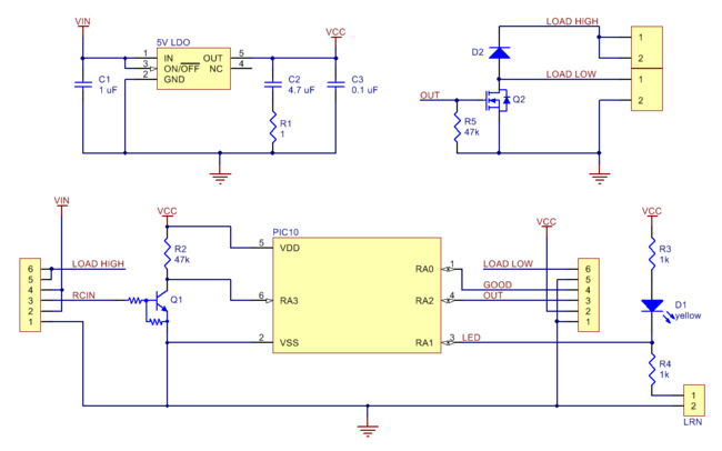
The schematic diagram of the Pololu RC Switch with Relay is shown below:
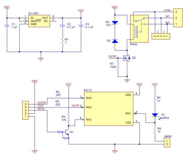 |
This schematic is also available as a printable pdf (165k pdf).
7. Pololu 4-Channel RC Servo Multiplexer
7.1. Pinout
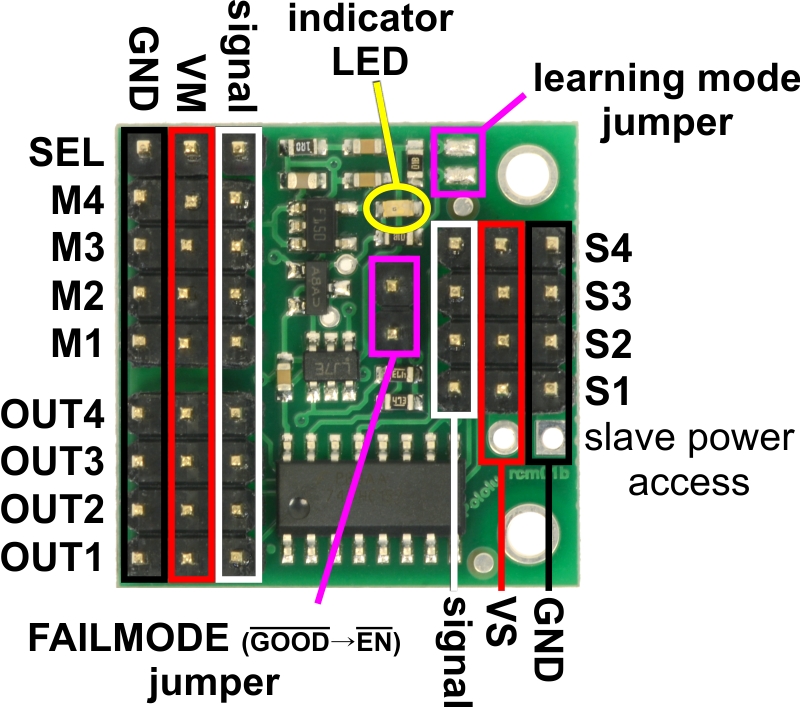 |
Pololu 4-Channel RC Servo Multiplexer (Assembled), labeled pinout. |
|---|
RC interface
The Pololu 4-Channel RC Servo Multiplexer has a total of 13 RC servo channels:
- The four inputs M1–M4 are called the master inputs.
- The four inputs S1–S4 are called the slave inputs.
- The four outputs OUT1–OUT4 are the main outputs of the device.
- The signal on the SEL input channel determines whether the outputs map to the master inputs or the slave inputs.
This guide uses the terms active, activated, and activation to refer to the active state of the switch. For the RC multiplexer, active means that the outputs reflect the slave inputs. By default, the switch will not be active and the master inputs will show up on the outputs.
Each servo channel consists of three pins: GND, power, and signal. As shown in the diagram above, the GND (ground) pins are on the edge of the board and the power pins are in the middle between GND and signal. All ground pins are internally connected on the board.
When the RC signal on the SEL channel is lost or invalid, the optional FAILMODE jumper determines the output behavior. If the jumper is left off, the master inputs will be in control. If the jumper is connected, the output channels go low and stay low for as long as the signal on the SEL channel remains invalid. For many servos and electronic speed controls (ESCs), a constant low on the signal line will turn them off, which might be desirable if the control signals are known to be bad.
Note that SEL is the only input that requires a valid RC servo signal (10–330 Hz pulse rate, 0.5–2.5 ms pulse width); the master and slave inputs can be general digital signals. For example, you could use OUT4 to control the brightness of a small (< 20 mA) LED by sending PWM signals to the inputs on S4 and M4.
The RC multiplexer pins are spaced 0.1″ apart so the servo inputs can be plugged directly into an RC receiver or servo controller using a Female-Female servo extension cable. These can be found in our Servo Cables category. The column of pins along the outside edge of the board is GND (ground) and the column in the middle is power.
We recommend that you connect the SEL and M1–M4 inputs to a single “master” RC device, such as an RC receiver or servo controller. The master device should have a power source that supplies power the RC multiplexer. The power supplied by the master should be between 2.5 and 16 V and it must be capable of supplying the current that the servos connected to the outputs draw.
We recommend that you connect the S1–S4 inputs to a single “slave” RC device, such as an RC receiver or servo controller. The slave device will need a source of power. You can either connect the slave power directly to the slave device or you can connect it to the GND/VS pin pair next to S1.
The OUT1–OUT4 outputs can be directly connected to standard RC servos.
The master RC device can use the SEL line to select which device controls the outputs. When the switch is active, the signal received on S1 will be reflected on OUT1, so a device sending pulses to S1 can control a servo or ESC connected to OUT1. When the switch is not active, OUT1 will reflect the input on M1. The same applies to channels 2–4.
Power
The power supplied by the master RC device should be between 2.5 and 16 V, and it must be capable of supplying the current that the servos connected to the outputs draw. The power pins of the SEL, M1–M4, and OUT1–OUT4 channels are all connected to the same VM rail, and the board draws its power from those pins. The power pins of the S1–S4 inputs are connected to each other on the VS rail but are not used by the board.
Additional outputs and indicator LED
The yellow indicator LED indicates what state the switch is in. The LED behavior is described in Section 9.
The FAILMODE jumper consists of two pins that might be individually useful to advanced users:
- The FAILMODE pin with the octagonal pad (the one closer to the edge of the board) is the GOOD output. This output is low when signal on the SEL input is valid, and high when the signal on the SEL input is invalid or missing.
- The other FAILMODE pin is the EN input. This input is pulled low by default. When this input is driven high, it disables all of the output channels, causing them to go low (0 V) and stay low.
The RC multiplexer has an internal signal named OUT that indicates whether the switch is activated or not. The OUT signal is high when the switch is active and is low otherwise. This signal is not accessible on any through-hole pin but you can access it by finding the 16-pin chip and soldering a wire to the pin 1, which is the pin that is closest to the OUT1 channel.
When high, all the output signals on the device will output a voltage approximately equal to 5 V or VM, whichever is lower. When low, these outputs will be at 0 V (ground). These outputs do not have resistors in series with them. Each output can source or sink up to 25 mA.
Configuration interface
The learning mode jumper can be used to get the device into learning mode and configure it. The configuration procedure is described in Section 10.
 |
Pololu 4-Channel RC Servo Multiplexer, bottom view with dimensions. |
|---|
Included hardware
The Pololu 4-Channel RC Servo Multiplexer is available in two versions:
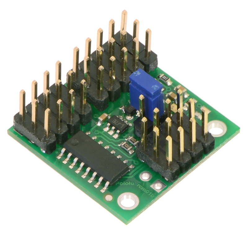
- The assembled version ships with the headers pins soldered in to every through-hole except the extra slave power connection pins, as shown in the left picture below. A shorting block is included for optional use with the FAILMODE jumper pins. The assembled version can be incorporated into an existing RC system without the need for any additional soldering. The header pin spacing is the same as on standard RC receivers, so the board works directly with standard hobby RC servos and servo cables.
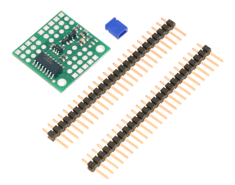
- The partial kit version gives you the flexibility to choose different connections. It includes a shorting block and two 1×25-pin male headers. These strips can be broken into smaller strips and soldered to the board, or wires can be soldered directly to the board for the most compact installation.
|
|
7.3. Schematic Diagram
The schematic diagram of the 4-Channel RC Servo Multiplexer is shown below:
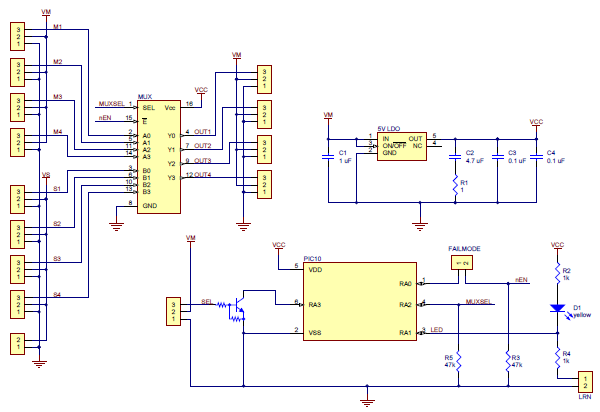 |
This schematic is also available as a printable pdf (210k pdf).
8. Functional Description
This section documents the functions and behavior of the RC switch. The information in this section is not needed to use the device, but it might be helpful if you are curious about the details.
Timing accuracy
The timing accuracy of the RC switch is limited by its internal clock, which has an accuracy of ±2%. Because of this, the threshold and other timing parameters might vary by a few percent.
Configuration parameters
The device stores two user-settable configuration parameters: threshold and inversion.
The threshold parameter is a pulse width that can range from 900 to 2100 μs and must be a multiple of 16 μs. The default threshold is 1696 μs.
The inversion parameter can either be enabled or disabled. When inversion is disabled, the pulses have to be above the threshold in order to activate the switch. When inversion is enabled, the pulses have to be below the threshold in order to activate the switch. By default, inversion is disabled.
Pulse measuring
The device measures standard RC pulses on its RC input (which is labeled RC IN or SEL depending on the device). It is designed to have strict requirements for the signal and to deactivate itself as soon as possible when those requirements are not met. The device expects the pulses to have a width within 500 to 2500 μs and a frequency within 10 to 333 Hz. These limits cannot be strictly enforced because of the ±2% clock accuracy, but the device is designed to accept any signal that is within these limits. If there has been no activity for 130 ms, the signal is considered to be bad. If there have been too many glitches detected on the RC input, the signal is considered to be bad.
The device requires three good pulses in a row before it will consider the signal to be good. However, as soon as the signal violates any of the rules above, it will consider the signal to be bad and deactivate the switch.
When comparing the measured pulse width to the threshold to determine whether the pulses are above or below the threshold, the device uses a hysteresis of ±64μs.
Safe-start
All of the RC switches except the Pololu 4-Channel RC Servo Multiplexer have a safe-start feature that reduces the likelihood of unexpected activation. Safe-start mode is active at power up, and while the safe-start mode is active, the switch does not activate. The device deactivates safe-start mode when the signal is good and it receives a pulse in the off position. The device will re-activate safe-start mode if the signal is bad continuously for 500 ms.
If the device is receiving a valid RC signal which suddenly stops, it will take 130 ms before the signal is recognized as bad. From there, it will take 500 ms before the safe-start mode becomes active, so there will be a total of 630 ms between the loss of the signal and the re-activation of safe-start mode.
To get out of safe-start mode and activate the switch, you should move the input to the off position and then move it to the on position.
Even with the safe-start feature, unexpected activation of the switch is still possible. With the Pololu RC Switch with Relay, one way this could happen is if the switch is activated but the logic power supply is at 3 V, which is too low to actually turn on the relay. If the logic power rises from 3 V to 5 V then the relay could turn on unexpectedly.
9. Outputs and Indicator LED
The OUT pin is an output that indicates whether the switch is active. A high value means the switch is active, and a low value means it is not active. The OUT pin is high whenever the integrated MOSFET or relay is turned on. The Pololu 4-Channel RC Multiplexer does not have an OUT pin, but the same signal could be accessed by soldering a wire to the board as described in Section 7.1.
The GOOD pin is an output that indicates whether the signal is valid (10–330 Hz pulse rate, 0.5–2.5 ms pulse width). When the GOOD pin is low, it means the signal is invalid. In that situation, the OUT pin will also be low. The RC multiplexer does not have a GOOD pin, but it does have an inverted GOOD pin as described in Section 7.1.
The yellow indicator LED shows what state the device is in. There are four states the device can be in during normal operation:
- If there is no input signal, the LED will blink with a 50% duty cycle and a period of 1 s. In this case, the OUT and GOOD pins will be low.
- If the pulses are in the on position but the switch is not active because safe-start mode is active, the LED will do a double-blink with a period of 1 s. In this case, the OUT pin will be low and the GOOD pin will be high.
- If the pulses are in the off position, the output will be off and the LED will do a brief blink once per second. In this case, the OUT pin will be low and the GOOD pin will be high.
- If the pulses are in the on position and the output is on, the LED will be mostly on and blink off briefly once per second. In this case, the OUT and GOOD pins will be high.
If the power supply voltage drops too low, the device will detect this and stop running. This is called a brown-out reset. After the power supply voltage recovers (which could be a few milliseconds later), the device will suspend normal operation briefly and do a special LED blink. The blink consists of a single blink followed by a double blink, with a period of 7/8 s and three repetitions.
During learning mode, the LED exhibits several other types of blinking. These are documented in Section 10.
10. Configuring Your RC Switch
The RC switch has two user-settable configuration parameters, threshold and inversion, which are described in Section 8. This section and the following sections explain how to set both parameters.
To configure the device, you will need to be able to connect and disconnect the two parts of the learning mode jumper. This will be required at several points by the instructions in the following sections.
|
Pololu RC Switch with Digital Output, labeled top view. |
|---|
For the Pololu RC Switch with Digital Output, the learning mode jumper consists of a pair of exposed pads on the component side of the board. To connect the two pads, you can use a wire, screwdriver, or some other conductive tool.
|
Pololu RC Switch with Small Low-Side MOSFET, top labeled view. |
|---|
For the Pololu RC Switch with Small Low-Side MOSFET, the learning mode jumper consists of a pair of exposed pads on the component side of the board. An alternate learning mode jumper is available on the other side of the board and is labeled “LRN”; you can use whichever jumper is more convenient. To connect the two pads, you can use a wire, screwdriver, or some other conductive tool.
|
Pololu RC Switch with Medium Low-Side MOSFET, labeled top view. |
|---|
For the Pololu RC Switch with Medium Low-Side MOSFET, the learning mode jumper consists of a pair of exposed pads on the component side of the board. An alternate learning mode jumper is available on the other side of the board and is labeled “LRN”; you can use whichever jumper is more convenient. To connect the two pads, you can use a wire, screwdriver, or some other conductive tool.
 |
Pinout of the Pololu RC Switch with Isolated Solid State Relay/Switch, SPST. |
|---|
For the Pololu RC Switch with Isolated Solid State Relay, the learning mode jumper consists of a pair of exposed pads on the component side of the board labeled “LRN”. To connect the two pads, you can use a wire, screwdriver, or some other conductive tool.
 |
Connecting a 1×2-pin male header to a blue shorting block makes a tool that can be used to activate the learning mode on the Pololu RC Switch with Relay. |
|---|
|
Pololu RC Switch with Relay, labeled top view. |
|---|
For the Pololu RC Switch with Relay, the learning mode jumper consists of two holes. You could use a wire to connect the two holes, but we recommend inserting a 1×2-pin male header into the included blue shorting block and using that as a tool to connect the two holes. The assembled version of the switch comes with a 1×2-pin male header. If you have the partial kit version, you can break two pins off of the included male header to get a 1×2-pin piece. To make the contact, stick the two exposed pins into the two holes of the learning mode jumper and then tilt the tool towards the side and press on it to ensure a good connection with the inside edge of each hole. It is not sufficient to just rest the tool on the learning mode jumper; you must tilt it and apply some force.
|
Pololu 4-Channel RC Servo Multiplexer (Assembled), labeled pinout. |
|---|
For the Pololu 4-Channel RC Servo Multiplexer, the learning mode jumper consists of a pair of exposed pads on the component side of the board. An alternate learning mode jumper is available on the other side of the board and is labeled “LEARN”; you can use whichever jumper is more convenient. To connect the two pads, you can use a wire, screwdriver, or some other conductive tool.
10.1. General Configuration Procedure
This is the general procedure for configuring the device. To follow these instructions, you will need to know how to connect and disconnect the learning mode jumper, as described in Section 10.
- Get the device into learning mode. In order to do this, power off the device, connect the learning mode jumper, and then power it on. After it is powered on, disconnect the learning mode jumper. At this point, you will see the indicator LED fading in and out with a period of 1 second. Your device is now in learning mode, and will be until you next turn off the power. In learning mode, it will not turn on the relay. If you want to abort learning mode, you can power off the device at this point and none of your settings will change.
- Tap the learning mode jumper (connect it and then disconnect it). This restores all of the settings in the device to their default values; the threshold will be 1696 μs and inversion will be disabled. The indicator LED should be blinking a different pattern now. If you want to use the default settings and exit learning mode, you can power off the device at this point and skip the instructions below.
- Now the device is in the pulse-measuring phase of learning mode. This is where you can choose what threshold to use.
- If you want to use the default threshold, you should not send RC pulses to the device. The device will indicate that the RC input signal is not recognized by blinking the LED with a 50% duty cycle and a period of 0.5 s.
- If you want to use a custom threshold, you should send RC pulses to the device. The device will indicate that it recognizes the RC input signal by blinking the LED with a special pattern that consists of a fade in followed by a blink, with a period of 2 s. The device will calculate the minimum and maximum pulse widths seen during this phase of learning mode, and set the threshold equal to the point midway between them (the average). In general, we recommend moving your input to both the off position and the on position during this phase of learning mode, and not moving it anywhere outside of that range. However, if you are using a servo controller to send pulses, you might want to simply send pulses equal to the desired threshold. If you accidentally send incorrect pulses, you will have to power off the device and start over at step 1.
- Tap the learning mode jumper again to save the chosen threshold. If the threshold you chose was not within the allowed range of 900 to 2100 μs, then the device will indicate an error by blinking the LED rapidly eight times per second. If that error happens, the threshold will not be saved and you should power off the device and try the procedure again with a different threshold. If the threshold you chose was within the allowed range, then it will be saved to non-volatile memory and you will see the LED fade in repeatedly with a period of 1 s.
- You can now chose whether to enable inversion. If you do not want to enable inversion, simply power off the device now to exit learning mode. If you do want to enable inversion, tap the learning mode jumper again. The LED will start fading out repeatedly with a period of 1 s.
- Power off the device to exit learning mode. Your learning mode jumper connection should be removed at this point. The settings you chose have been saved in non-volatile memory of the device and you can power it on to use the new settings.
10.2. Restoring the Default Settings
This section gives steps for restoring the switch to its default settings. This is a good thing to try if you have any trouble using the switch. The general configuration procedure is documented in Section 10.1, but the instructions here are easier to follow if you just want to restore the device to its default settings. To follow these instructions, you will need to know how to connect and disconnect the learning mode jumper, as described in Section 10.
- Get the device into learning mode. In order to do this, power off the device, connect the learning mode jumper, and then power it on. After it is powered on, you should disconnect the learning mode jumper. At this point, you will see the indicator LED fading in and out with a period of 1 second.
- Tap the learning mode jumper (connect it and then disconnect it). The indicator LED should be blinking a different pattern now.
- Power off the device to exit learning mode.
After following these instructions, the threshold should be 1696 μs and inversion should be disabled.
10.3. Enabling Inversion
This section gives steps for enabling inversion while still using the default threshold of 1696 μs. The general configuration procedure is documented in Section 10.1, but the instructions here are easier to follow if you just want to enable inversion and are happy with the default threshold value. To follow these instructions, you will need to know how to connect and disconnect the learning mode jumper, as described in Section 10.
- Since you don’t want to set the threshold, you should stop sending RC pulses to the device. If you are controlling the switch with an RC receiver, you might need to power off the transmitter and power cycle the receiver. If possible, you could just disconnect the wire going to the RC IN pin.
- Get the device into learning mode. In order to do this, power off the device, connect the learning mode jumper, and then power it on. After it is powered on, you should disconnect the learning mode jumper. At this point, you will see the indicator LED fading in and out with a period of 1 second.
- Tap the learning mode jumper (connect it and then disconnect it). The indicator LED should be blinking with a 50% duty cycle and a period of 0.5 to indicate that there is no signal being received. If you see it doing a pattern where it fades in and then blinks, then you are still sending pulses to the device. You should figure out how to stop sending pulses, and start over at step 1.
- Tap the learning mode jumper again. The LED should now be fading in repeatedly with a period of 1 s.
- Tap the learning mode jumper again. The LED should start fading out repeatedly with a period of 1 s.
- Power off the device to exit learning mode.
Related products


Home | Forum | Blog | Support | Ordering Information | Lists | Distributors | BIG Order Form | About | Contact
© 2001–2026 Pololu Corporation
