Support » Pololu Dual MC33926 Motor Driver Shield User’s Guide » 6. Customizing the Shield »
6.b. Accessing nD2 and nSF Pins Separately for Each Channel
The shield combines the two motor driver chips’ D2 and SF pins in order to decrease the number of I/O lines required to control the motors. The combined lines are sufficient for most applications, but you can modify the board to get independent access to the MxD2 and MxSF pins if you want the additional control and information.
There are two pairs of 0.1″-spaced holes on the shield labeled “D2 1=2” and “SF 1=2”. These pairs are connected on the underside of the PCB by a thin trace, with the holes labeled “M1” connecting to the M1 driver and the holes labeled “M2” connecting to M2 driver.
 |
Cuttable traces on the dual MC33926 motor driver shield for accessing nD2 and nSF separately on each driver IC. |
|---|
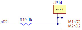
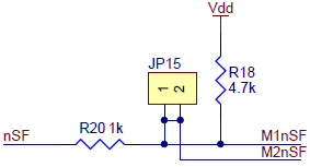
The following diagrams shows the relevant sections of the board schematic:
 |
 |
To separately access both the pins, you can use a knife to cut the trace between the through-hole pair.
For D2, note that once the connection between the two pins is severed, only M1D2 will have the protection resistor between it and the logic connections.
For SF, note that once the connection between the two pins is severed, only M1SF will have the required pull-up resistor and the protection resistor between it and the logic connections; you will need to add a separate pull-up resistor and protection resistor for M2SF.
You can later use a shorting block to restore the default combined D2 or SF lines if you populate the severed hole pair with a 2×1 piece of the included 0.1″ male header strip.
Related products


Home | Forum | Blog | Support | Ordering Information | Lists | Distributors | BIG Order Form | About | Contact
© 2001–2026 Pololu Corporation
