Support » Pololu Dual MC33926 Motor Driver Shield User’s Guide » 3. Getting Started with an Arduino »
3.c. Shield Connections: Signals, Power, and Motors
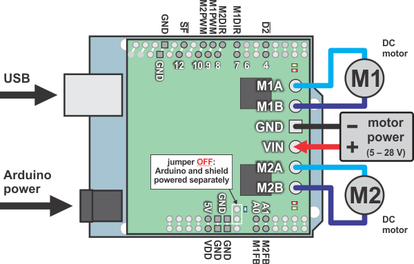 |
Using the dual MC33926 motor driver shield with an Arduino (shield and Arduino powered separately). |
|---|
All of the necessary logic connections between the Arduino and the motor driver shield, including VDD, are made automatically when the shield is plugged into the Arduino. However, the shield’s motor power must be supplied directly to the shield itself via its large, high-current VIN and GND pads. The motor channels, located on either side of these power pins, can each be used to independently control a bidirectional brushed DC motor. Each motor channel is comprised of a pair of pins—MxA and MxB—that connect to the two terminals of a DC motor and can deliver a continuous 3 A (5 A peak). The picture above shows the typical connections involved in using this board as an Arduino shield. In the depicted configuration, the Arduino is powered separately from the shield, such as through its USB connector or power jack.
Default Arduino Pin Mappings
The following table shows how the shield connects your Arduino’s pins to the motor drivers’ pins:
| Arduino Pin | Shield Pin Name | Basic Function |
|---|---|---|
| Digital 4 | D2 (or nD2) | Tri-state disables both outputs of both motor channels when LOW; toggling resets latched driver fault condition |
| Digital 7 | M1DIR | Motor 1 direction input |
| Digital 8 | M2DIR | Motor 2 direction input |
| Digital 9 | M1PWM | Motor 1 speed input |
| Digital 10 | M2PWM | Motor 2 speed input |
| Digital 12 | SF (or nSF) | Status flag indicator (LOW indicates fault) |
| Analog 0 | M1FB | Motor 1 current sense output (approx. 525 mV/A) |
| Analog 1 | M2FB | Motor 2 current sense output (approx. 525 mV/A) |
See Section 4.b for more detailed descriptions of the shield pins and a motor control truth table. See Section 5 for a schematic diagram of the shield. See Section 6.a for instructions on how to customize your board’s Arduino pin mappings if the above defaults are not convenient.
Power Connections
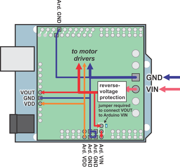 |
Dual MC33926 motor driver shield power buses when connected to an Arduino. |
|---|
In the shield’s default state, the motor driver shield and Arduino are powered separately. When used this way, the Arduino must be powered via USB, its power jack, or its VIN pin, and the shield must be supplied with 5 to 28 V through the large VIN and GND pads on the right side of the board. Attempting to power the shield through other means, such as from the Arduino or through the small VOUT pin, can permanently damage both the Arduino and the shield (only the large power traces on the right side of the shield are designed to handle the high currents involved in powering motors). A high-side reverse-voltage protection MOSFET prevents the shield from being damaged if motor power is inadvertently connected backwards. Logic power, VDD, is automatically supplied by the Arduino.
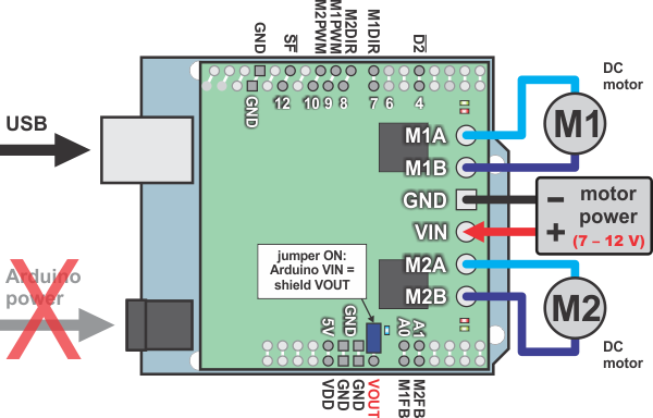 |
Using the dual MC33926 motor driver shield with an Arduino (Arduino powered by shield). |
|---|
It is also possible to power your Arduino directly from the motor shield, as shown in the diagram above, which eliminates the need for a separate Arduino power supply. When the ARDVIN=VOUT shorting block is in place, the shield’s reverse-protected input power, VOUT, is connected to the Arduino’s VIN pin. (When power is connected properly, VOUT is essentially the same as the shield’s VIN.) The Arduino’s power jack must remain disconnected at all times in this configuration.
Warning: When powering the Arduino from the motor shield, you must never connect a different power supply to the Arduino’s VIN pin or plug a power supply into the Arduino’s power jack, as doing so will create a short between the shield’s power supply and the Arduino’s power supply that could permanently damage both the Arduino and the motor shield. In this case, it is also important that your shield power supply is an acceptable voltage for your Arduino, so the full shield operating voltage range of 5 – 28 V probably will not be available. For example, the recommended operating voltage of the Arduino Uno is 7 – 12 V.
Note that the shorting block just routes the motor power to the Arduino VIN pin, so plugging in USB with this shorting block in place is just like plugging in USB with the Arduino powered from its power jack. On standard Arduinos we recommend against plugging a powered Arduino into USB (see this forum post for more information), but on some Arduino-compatible boards such as the A-Stars, this is completely safe.
Power Considerations
The shield operates from 5 to 28 V, but it can tolerate transient voltages (shorter than 500 ms in duration) of up to 40 V, which means it is generally safe to power this board with a 24 V battery. At voltages between 5 and 8 V, the shield performance is derated, and the maximum achievable continuous output current will be decreased (according to the MC33926 datasheet, H-bridge MOSFET on-resistances might increase by 50% in this “quasi-functional” performance region). The shield operating voltage range is much wider than the typical Arduino operating voltage range, so if you are using the shield to power your Arduino, please ensure that your voltage source is within acceptable limits for your Arduino as well as the shield.
It is important that you use a power source that is capable of delivering the current your motors will require. For example, alkaline cells are typically poor choices for high-current applications, and you should almost never use a 9V battery (the rectangular type with both terminals on the same side) as your motor power supply. We recommend NiMH batteries, lithium-based rechargeable batteries (if you have a good charger and adequately understand the dangers of using them improperly), or a power adapter with an appropriate power rating. The current draw is ultimately a function of your motors, your operating voltage, and your motor load, but the driver is capable of delivering a continuous 6 A (3 A per channel), and it can deliver in excess of 10 A before the internal current limiting is activated.
Shield Power Dissipation
Each MC33926 motor driver IC has a maximum continuous current rating of 5 A. However, the actual current it can deliver depends on how well you can keep it cool. The shield’s printed circuit board is designed to draw heat out of the motor driver chips, but performance can be improved by adding heat sinks.
Unlike other H-Bridges, the MC33926 has a feature that allows it to gracefully reduce current as the current exceeds 5 A or as the chip temperature approaches its limit. This means that if you push the chip close to its limit, you will see less power to the motor, but it might allow you to avoid a complete shutdown.
We tested the shield at room temperature with no forced air flow or heat sinks. In our tests, the shield was able to deliver 5 A to both channels simultaneously for 10 s before the thermal protection started reducing the current. The shield delivered 4 A on both channels for 37 s, and at 3 A it was able to operate continuously for over 10 minutes without triggering current limiting or thermal protection.
Our tests were conducted at 100% duty cycle; PWMing the motor will introduce additional heating proportional to the frequency.
This product can get hot enough to burn you long before the chip overheats. Take care when handling this product and other components connected to it.
Motor Considerations
If your motor has a stall current over the driver’s continuous current rating of 3 A per channel, we recommend you take extra steps to make sure that your motor will not be exposed to loads that will cause it to exceed 3 A for prolonged periods of time (or you take extra steps to keep the motor drivers cool, such as increasing air flow or adding heat sinks). Exceeding 3 A for long durations should not damage the shield, but it will eventually activate the driver’s thermal protection, which might result in inadequate performance for your application.
It is not unusual for the stall current of a motor to be an order of magnitude (10×) higher than its free-run current. If you do not know your motor’s stall current, you can approximate it by measuring the current it draws while held stalled at a lower voltage (such as when powered from a single battery cell) and then scaling that value linearly with voltage. For example, the stall current of a motor at 6 V is six times the stall current of that motor at 1 V. Another, less accurate method is to use a multimeter to measure the resistance between the motor terminals and then use Ohm’s law to compute the stall current I at voltage V: I = V/R. This last method generally is not as reliable because it can be difficult to measure such small resistances accurately.
Occasionally, electrical noise from a motor can interfere with the rest of the system. This can depend on a number of factors, including the power supply, system wiring, and the quality of the motor. If you notice parts of your system behaving strangely when the motor is active, first double-check that your power supply is adequate, then consider taking the following steps to decrease the impact of motor-induced electrical noise on the rest of your system:
|
||
|
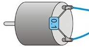
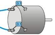
- Solder a 0.1 µF ceramic capacitor across the terminals of your motors, or solder one capacitor from each terminal to the motor case (see the pictures to the right). For the greatest noise suppression, you can use three capacitors per motor (one across the terminals and one from each terminal to the case).
- Make your motor leads as thick and as short as possible, and twist them around each other. It is also beneficial to do this with your power supply leads.
- Route your motor and power leads away from your logic connections if possible.
- Place decoupling capacitors (also known as “bypass capacitors”) across power and ground near any electronics you want to isolate from noise. These can typically range from 10 uF to a few hundred uF.
Related products


Home | Forum | Blog | Support | Ordering Information | Lists | Distributors | BIG Order Form | About | Contact
© 2001–2026 Pololu Corporation
