Next:
3.c.
Shield Connections: Signals, Power, and Motors
Previous:
3.a.
What You Will Need
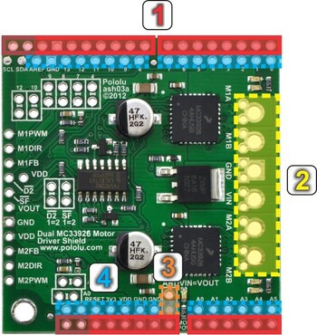 |
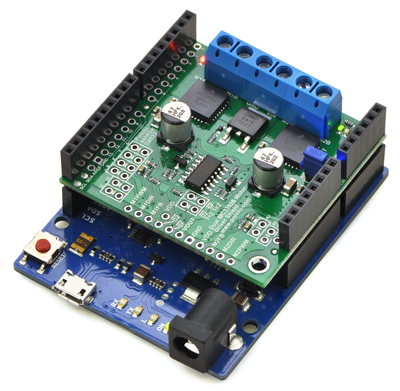
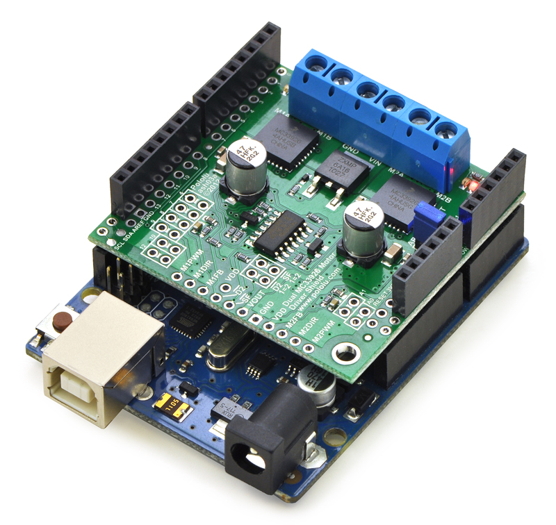
- Stackable Arduino headers: Before you can use this board as an Arduino shield, you need to solder four of the five included Arduino header strips to the set of holes highlighted in red in the picture above. The headers should be oriented so that the female sockets rest on the top side of the shield and face up while the male pins protrude down through the board, and the solder connections should be made on the underside of the shield. Newer Arduinos, including the Uno R3 and the Leonardo, use one 10×1 header, two 8×1 headers, and one 6×1 header, as shown in the left picture below. If you happen to have an older Arduino that lacks the new pins introduced when the Uno R3 was released, you should assemble the shield with two 8×1 headers and two 6×1 headers; the right picture below shows an example of the shield assembled in this way (note: the shield can still be used with newer Arduinos when assembled in this way, and it is actually plugged into an Uno R3 in the picture). In short, the two pairs of pins highlighted above in darker red should not be populated if you are using this board with an older Arduino that does not support these additional pins. Please make sure you solder the appropriate headers for your particular Arduino!
- Motor and power connections: The six large holes/twelve small holes on the right side of the board, highlighted in yellow in the above diagram, are the motor outputs and power inputs. You can optionally solder the included 5mm-pitch terminal blocks to the six large holes to enable temporary motor and motor power connections, or you can break off a 12×1 section of the included 0.1″ header strip and solder it into the smaller through-holes that border the six large motor and motor power pads. Note, however, that each header pin pair is only rated for a combined 6 A, so for higher-power applications, the terminal blocks should be used or thick wires with high-current connectors should be soldered directly to the board. The smaller holes are intended only for 0.1″ header pins, not for the terminal blocks!
- Arduino power jumper: If you want the option of powering your Arduino and motor shield from the same source, you can solder a 2×1 piece of the included 0.1″ male header strip to two the pins highlighted in orange in the above picture. Shorting across these pins with the included shorting block will connect the shield power to the Arduino’s VIN pin. You should not use this to power the shield from the Arduino as this connection is not designed to handle high currents, and you must never supply power to the Arduino’s VIN pin or power jack while this shorting block is in place, because it will create a short between the shield power supply and the Arduino power supply and will likely permanently damage something.
- Arduino pin breakout points: The shield provides a secondary access point for each Arduino pin, divided into two rows of pins spaced on a 0.1″ grid (unlike the standard Arduino pins, which have a half-pin offset introduced by the gap in the top row). You can optionally solder 0.1″ female headers (not included) to these pins. Note that the SCL and SDA breakouts are top-layer pads only, not through-holes, due to the close proximity of Arduino pins below.
The other through-holes on the shield are used for more advanced things like customizing the Arduino pin mappings or using the board with other microcontrollers. They are not necessary for getting started using this shield with an Arduino, and they are discussed in more detail later in this guide.
Next:
3.c.
Shield Connections: Signals, Power, and Motors
Previous:
3.a.
What You Will Need