Support » Sample Project: Simple Hexapod Walker »
3. Construction
Step 1: Attach male header as a battery connector.
Find the 1×10 piece of 0.1" male header included with your Maestro. Break off a 1×2 piece and solder it to the BAT and GND pins as shown. Note that the connector is not polarized, so you must be careful to always plug in the battery with the black wire connected to ground and the red wire connected to BAT.
The connector shown in the picture is from an old version of the battery. The new one will look different, but the black and red wires should still connect to the same pins on the Maestro.
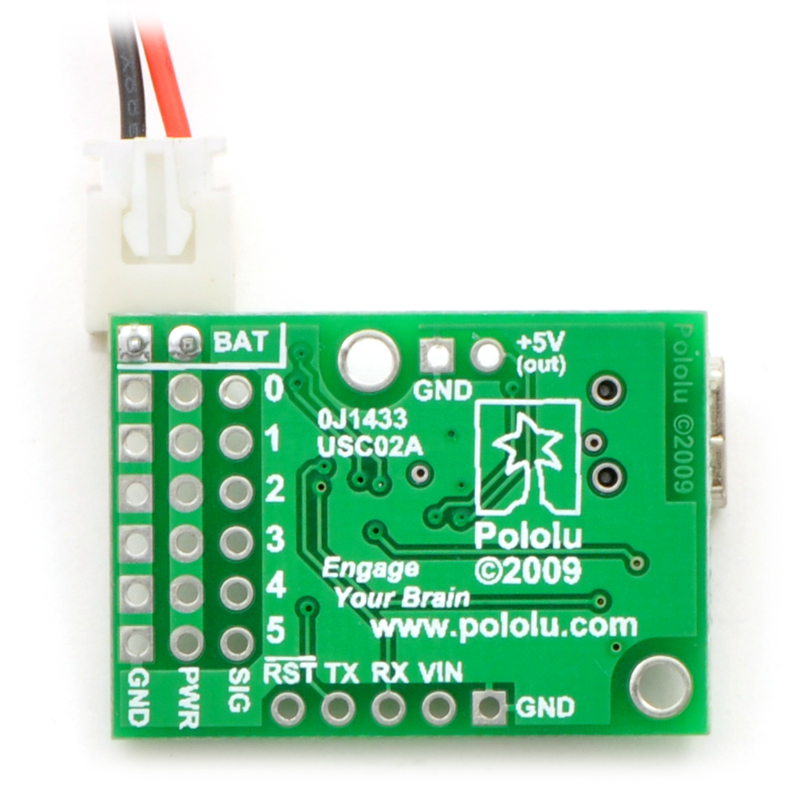 |
Soldering a power connector to the Micro Maestro. |
|---|
Step 2: Set up the Maestro for self power.
With your battery disconnected, attach a wire (red) from the positive terminal of the male header to VIN. Take care not to short or damage any of the components on the board. Now, with the battery plugged in, your Maestro should be powered-up and slowly flashing its yellow LED, indicating that it is waiting to detect the baud rate on the serial communication. You will not be using serial communication for this project, so you need to disable baud rate detection in the next step.
The connector shown in the picture is from an old version of the battery. Since you will be using male header, which completely covers the holes on the board, solder to the exposed part of the header pin.
 |
Self power and a battery connector on the Micro Maestro. |
|---|
Step 3: Verify that the Maestro and servos are functioning.
The Maestro Control Center is used for configuration and control of the Micro Maestro, for testing, debugging, scripting, and more. See Section 4 of the Micro Maestro User’s Guide for complete instructions on using the Maestro Control Center.
Launch the Maestro Control Center and configure your Maestro for “USB Dual Port” mode. The yellow LED should now be mostly off, flashing very briefly about once per second. On the Status tab, enable servo ports 0, 1, and 2, and the yellow LED will start double-blinking, indicating that some ports are active.
Next, using a piece of male header (included with the Maestro), temporarily connect a servo to port 0. Make sure to connect the wires correctly, with the brown or black wire connected to ground. You should hear a short high-pitched whine as the servo activates, moving to and holding a position in the middle of its range. After a fraction of a second, when the servo has reached its position, it should be silent. Move the slider from 1000 μs to 2000 μs to test the motion of the servo. Test all three ports and all three servos before continuing with the assembly.
Configure each of the servo ports to “Go to” 1500 μs on startup. This will make it easier to align the legs later on.
Configure ports 3, 4, and 5 to be inputs. This is important, since you will be connecting sensors later and want to avoid shorting them out!
Disconnect the battery before continuing.
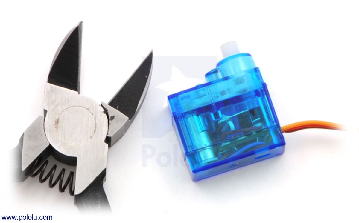 |
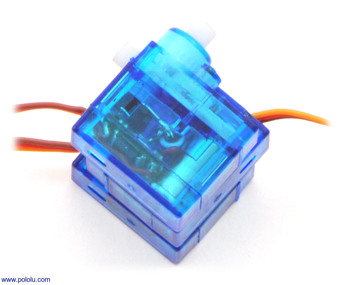
A sub-micro servo with mounting tabs clipped off. |
|---|
Step 4: Construct the body by gluing the servos together.
Remove the mounting tabs from all three servos with diagonal cutters. The tabs are not needed for this project and can interfere with the motion of the servos.
Next, join the servos with a few dabs of hot glue as shown below. You do not need much glue to hold them securely! Try to align the corners precisely to make flat surfaces for mounting the other parts.
 |
Try to align the corners. |
|---|
Clip the servo cables, leaving at least 2" (more if you are less experienced with soldering). Strip a small amount of wire from the end of each cable.
 |
Cut and strip the servo leads, leaving about 2" of wire. |
|---|
Step 5: Solder the servos and sensors to the Micro Maestro.
This step requires patience and care. A second pair of hands could be very useful.
Use solder to tin the leads of the servos so that they can be connected initially without additional solder. Looking at the pictures below for reference, place the Maestro on the back side of the body and place the middle wires over the front of the Maestro and into the holes for channel 1. Holding the wires in these holes, pull the Maestro away from the body, then touch the soldering iron to each connection so that the small amount of solder on the wires melts and holds them in place. You should now be able to add more solder to each of the connections, until the holes are filled and the wires are held securely. Check carefully for loose strands of wire, which could cause shorts.
Continue, soldering the right servo to channel 0 and the left servo to channel 2, so that the servos are arranged in the same relative positions as the ports.
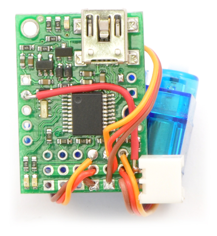 |
Connecting the servos to ports 0, 1, and 2 on the Micro Maestro. |
|---|
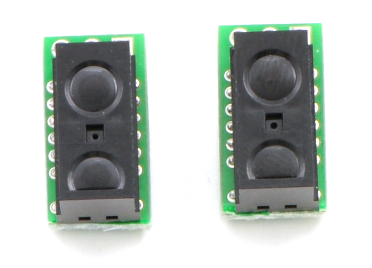 |
Digital distance sensors with trimmed carrier boards. |
|---|
Cut the sensor boards with a rotary tool, grinding wheel, diagonal cutters, or a jeweler’s saw, removing the part containing the unneeded mounting hole, so that they are as small as possible. (Make sure you do not cut any traces.) Then solder them to a cable so that you can connect them to the Maestro. The example below uses a 4-wire ribbon cable, sharing the power and ground connections for the two sensors. Ribbon cable makes the assembly relatively clean, but you can use whatever wire you have available. Look ahead in the instructions to see where the sensors are going to go, and make sure that you have a long enough cable. Think about how to keep the wires close to the body and out of the way of the legs and servos.
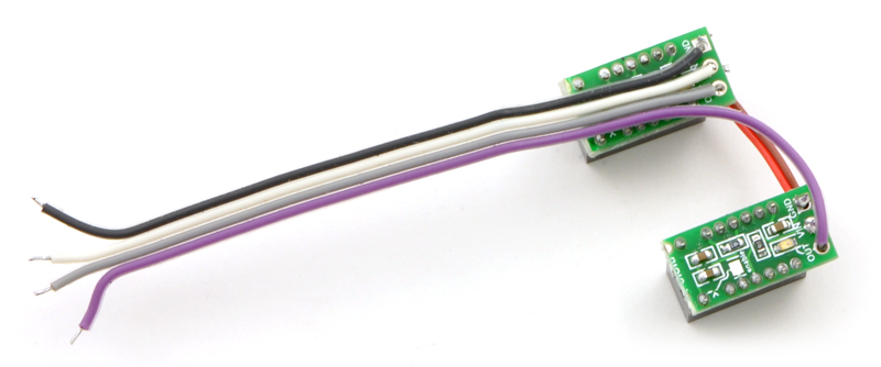 |
Soldering the sensors to a four-pin cable. |
|---|
Solder the sensor power and ground to +5V and ground on the Maestro, and connect the outputs of the right and left sensors to channels 3 and 4, respectively. Note that we use +5V instead of the battery voltage so that the Maestro channels will never see higher voltages – and another benefit is that the sensors will work under USB power, without the battery plugged in.
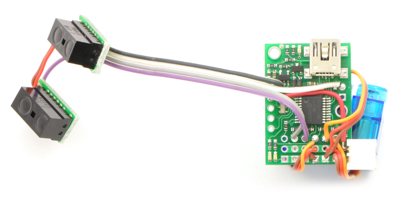 |
Soldering the sensor cable on to the Maestro. |
|---|
You now have a complete electrical assembly. Plug in the batteries, and the sensors should become active, turning on their red LEDs whenever they detect an object within 10 cm. With the Maestro control center, you should be able to see the input value change from 255, when no object is present, to a low value of 40 or so, when an object is detected. If the LEDs are always on, you probably forgot to set the ports to inputs in Step 3.
Step 6: Construct the legs.
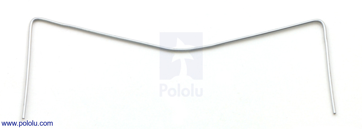
Unfold the paper clips into straight pieces of wire. Pliers make ugly dents in the metal, so try to use your fingers and the edge of a table to do this.
 |
Straighten the paper clips as much as possible. |
|---|
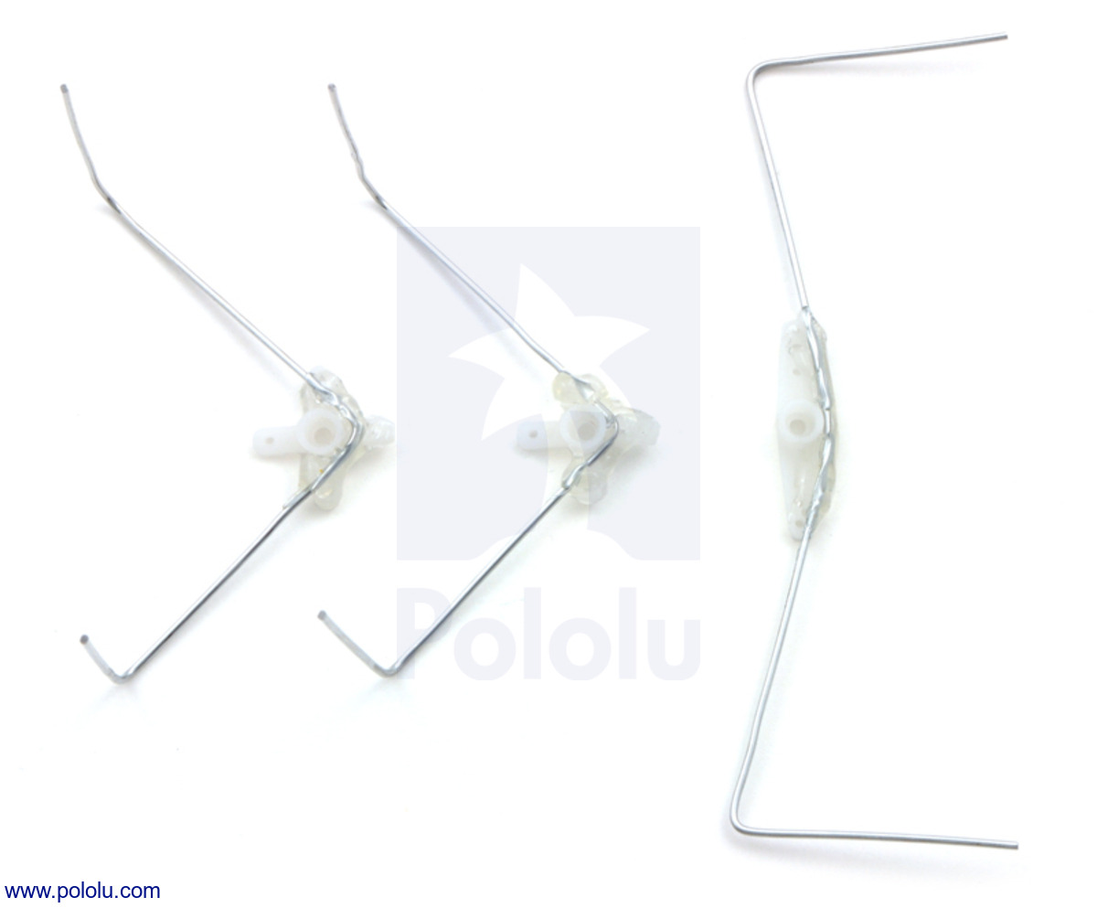
The wires should be six inches long. To make the front and back legs, fold two of them into 1.5" sections, with 90° angles between the sections, like this:
 |
The front and back legs of the hexapod. The segments at the end should be 1.5" in length. |
|---|
Fold the third piece into an M shape, with sections of length 1.25", 1.75", 1.75", and 1.25", like this:
 |
The middle legs of the hexapod. The segments at the end should be 1.25" in length. |
|---|
Hot-glue the legs onto servo horns. Use a straight horn for the middle legs and cross-shaped or round horns for the front and back legs.
 |
Gluing the hexapod legs to servo horns. |
|---|
With battery power connected, so that the servos hold their neutral positions, put the horns onto the servos so that the legs are as close as possible to neutral positions, as shown in the picture. Fix them in place with the included screws, holding the legs as you tighten them so that you do not apply torque to the fragile servo gears. Glue the Maestro to the back side of the servos, flush with the bottom.
 |
Attaching the legs and Maestro to the servos. |
|---|
Important: Never apply torque to the legs with your hands, attempt to prevent them from moving, or backdrive them. Servo gears can be easily broken, so they should only ever move under their own power. Use the Maestro Control Center to experiment with different positions, instead of forcing the servos.
Step 7: Attaching the battery and sensors.
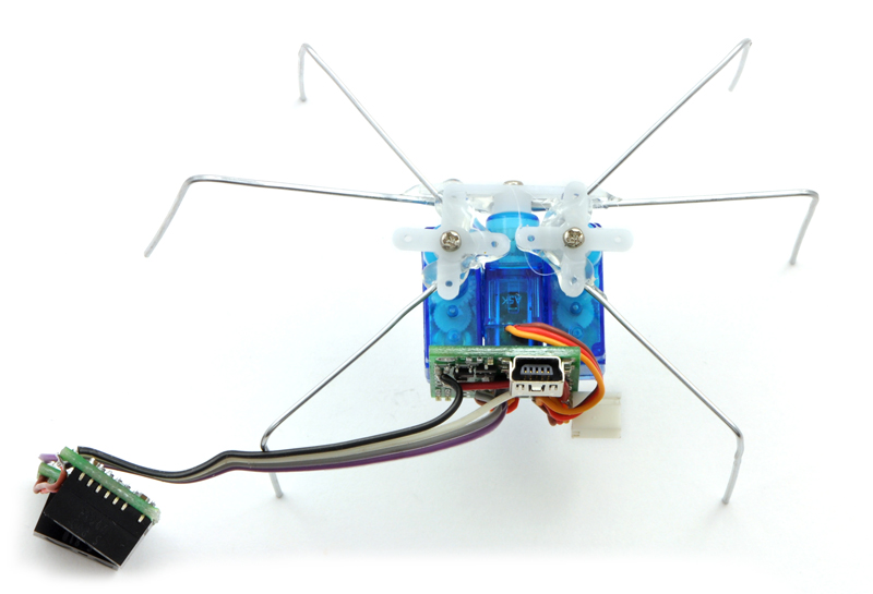
Glue the battery to the front of the hexapod, flush with the bottom, so that there will be as much clearance as possible. Make sure that the middle legs have plenty of room to turn left and right without hitting the battery. Glue the sensors to the top of the battery, angled to the left and right.
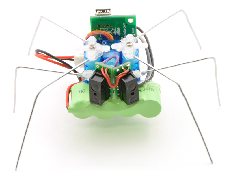 |
The assembled hexapod, front view. |
|---|
Take care that the wiring does interfere with the motion of the middle legs. You might want to route yours differently. Use small drops of hot glue as necessary to hold the wires in place.
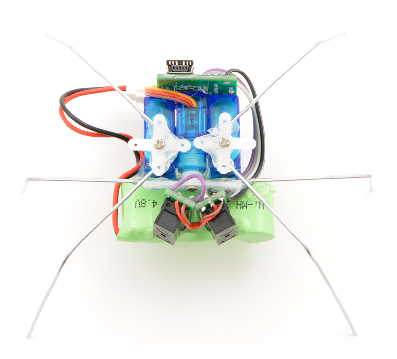 |
The assembled hexapod, top view. |
|---|
Step 8: Final touches.
Use the Maestro Control Center to find the neutral positions (where the legs are as symmetrically arranged as possible) as well as their safe minimums and maximums. Set the neutral positions as the “Go to” values for each servo, and set Min and Max values so that your hexapod will never destroy itself. Adjust the angles of the wires so that all six feet touch the ground in the neutral position, probably by bending the front and back legs to more than 90°.
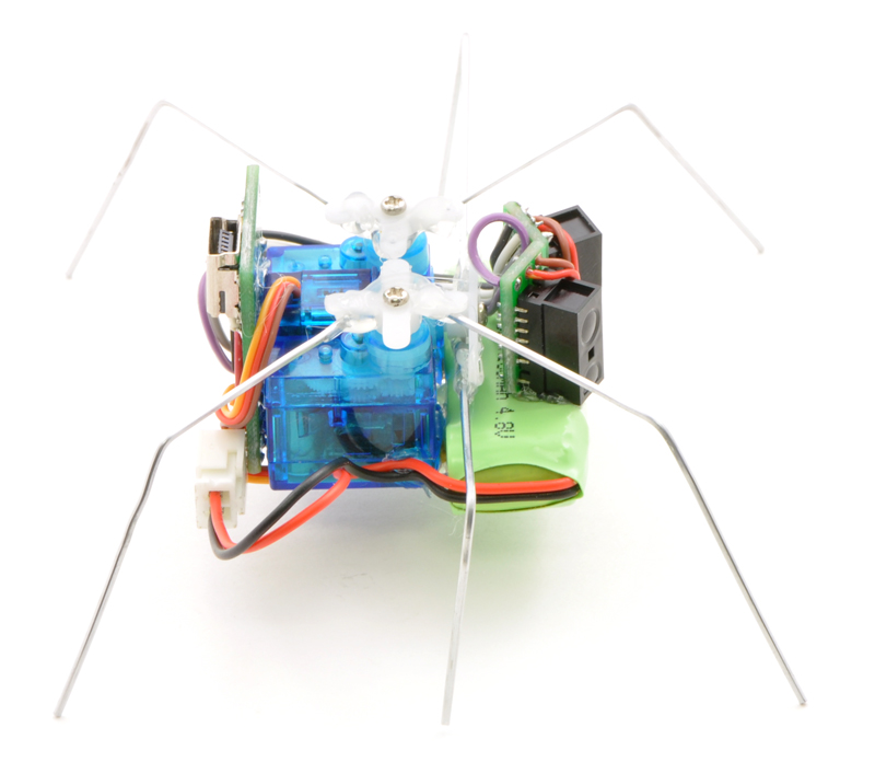 |
The assembled hexapod, side view. |
|---|
One final, optional thing that you might want to do is to add a dab of hot glue to each foot, so that the metal is less likely to scratch up your work surface. Your hexapod is now ready to be programmed!


Home | Forum | Blog | Support | Ordering Information | Lists | Distributors | BIG Order Form | About | Contact
© 2001–2026 Pololu Corporation
