Support » Pololu Maestro Servo Controller User’s Guide » 5. Serial Interface »
5.g. Daisy Chaining
This section is a guide to integrating the Maestro in to a project that has multiple TTL serial devices that use a compatible protocol. This section contains no new information about the Maestro: all of the information in this section can be deduced from the definitions of the three serial modes (Section 5.a) and the serial protocols used by the Maestro (Section 5.c).
First of all, you will need to decide whether to use the Pololu protocol, the Mini SSC protocol, or a mix of both. You must make sure that no serial command you send will cause unintended operations on the devices it was not addressed to. If you want to daisy chain several Maestros together, you can use a mixture of both protocols. If you want to daisy chain the Maestro with other devices that use the Pololu protocol, you can use the Pololu protocol. If you want to daisy chain the Maestro with other devices that use the Mini SSC protocol, you can use the Mini SSC protocol.
Secondly, assign each device in the project a different device number or Mini SSC offset so that they can be individually addressed by your serial commands. For the Maestro, this can be done in the Serial Settings tab of the Maestro Control Center application.
The following diagram shows how to connect one master and many slave devices together into a chain. Each of the devices may be a Maestro or any other device, such as a jrk, qik or other microcontroller.
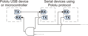 |
Daisy chaining serial devices using the Pololu protocol. An optional AND gate is used to join multiple TX lines. |
|---|
The Mini Maestro 12, 18, and 24 have a special input called TXIN that eliminates the need for an external AND gate (the AND gate is built in to the Maestro.) To make a chain of devices using the TXIN input, connect them like this:
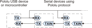 |
Daisy chaining serial devices that have a TXIN input. |
|---|
Using a PC and a Maestro together as the master device
The Maestro can enable a personal computer to be the master device. The Maestro must be connected to a PC with a USB cable and configured to be in either USB Dual Port or USB Chained serial mode. In USB Dual Port mode, the Command Port on the PC is used for sending commands directly to the Maestro, and the TTL Port on the PC is used to send commands to all of the slave devices. In the USB Chained mode, only the Command Port is used on the PC to communicate with the Maestro and all of the slave devices. Select the mode that is most convenient for your application or easiest to implement in your programming language.
Using a Maestro as a slave device
The Maestro can act as a slave device when configured to be in the UART serial mode. In this mode, commands are received on the RX line, and responses are sent on the TX line. A USB connection to a PC is not required, though an RX-only Comand Port is available on the PC for debugging or other purposes.
Connections
Connect the TX line of the master device to the RX lines of all of the slave devices. Commands sent by the master will then be received by all slaves.
Receiving serial responses from one of the slave devices on the PC can be achieved by connecting the TX line of that slave device to the RX line of the Maestro.
Receiving serial responses from multiple slave devices is more complicated. Each device should only transmit when requested, so if each device is addressed separately, multiple devices will not transmit simultaneously. However, the TX outputs are driven high when not sending data, so they cannot simply be wired together. Instead, you can use an AND gate, as shown in the diagram, to combine the signals. Note that in many cases receiving responses is not necessary, and the TX lines can be left unconnected.
Whenever connecting devices, remember to wire the grounds together, and ensure that each device is properly powered. Unpowered devices with a TTL serial port can turn on or partially on, drawing power from the serial line, which means that extra care must be taken when turning power off and on to reset the devices.
Sending commands
The Pololu Protocol or Mini SSC protocol should be used when multiple Pololu devices are receiving the same serial data. This allows the devices to be individually addressed, and it allows responses to be sent without collisions.
If the devices are configured to detect the baud rate, then when you issue your first Pololu Protocol command, the devices can automatically detect the baud from the initial 0xAA byte.
Some older Pololu devices use 0x80 as an initial command byte. If you want to chain these together with devices expecting 0xAA, you should first transmit the byte 0x80 so that these devices can automatically detect the baud rate, and only then should you send the byte 0xAA so that the Maestro can detect the baud rate. Once all devices have detected the baud rate, Pololu devices that expect a leading command byte of 0x80 will ignore command packets that start with 0xAA, and the Maestro will ignore command packets that start with 0x80.
Related products


Home | Forum | Blog | Support | Ordering Information | Lists | Distributors | BIG Order Form | About | Contact
© 2001–2026 Pololu Corporation
