Support » Pololu Maestro Servo Controller User’s Guide » 5. Serial Interface »
5.a. Serial Settings
The Maestro has three different serial interfaces. First, it has the TX and RX lines, which allow the Maestro to send and receive non-inverted, TTL (0 – 5 V) serial bytes (Section 5.b). Secondly, the Maestro shows up as two virtual serial ports on a computer if it is connected via USB. One of these ports is called the Command Port and the other is called the TTL port.
- In Windows, you can determine the COM port numbers of these ports by looking in your computer’s Device Manager.
- In Linux, the Command Port will usually be
/dev/ttyACM0and the TTL Port will usually be/dev/ttyACM1. These numbers may be different on your computer depending on how many serial devices are active when you plug in the Maestro. - In Mac OS X 10.7 (Lion) and later, the Maestro’s two virtual serial ports will have a name of the form /dev/cu.usbmodem<number>, for example
/dev/cu.usbmodem00654321. The one with the lower number is the Command Port.
This section explains the serial interface configurations options available in the Serial Settings tab of the Maestro Control Center.
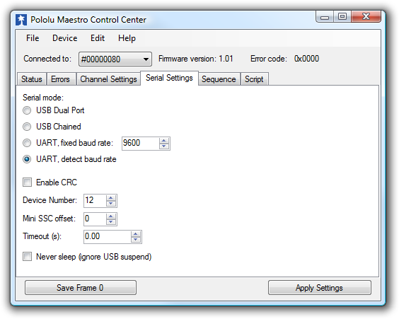 |
The Serial Settings tab in the Maestro Control Center. |
|---|
The Maestro can be configured to be in one of three basic serial modes:
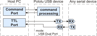 |
The USB Dual Port serial mode. |
|---|
USB Dual Port: In this mode, the Command Port can be used to send commands to the Maestro and receive responses from it. The baud rate you set in your terminal program when opening the Command Port is irrelevant. The TTL Port can be used to send bytes on the TX line and receive bytes on the RX line. The baud rate you set in your terminal program when opening the TTL Port determines the baud rate used to receive and send bytes on RX and TX. This allows your computer to control the Maestro and simultaneously use the RX and TX lines as a general purpose serial port that can communicate with other types of TTL serial devices.
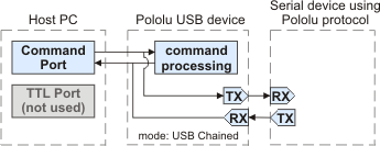 |
The USB Chained serial mode. |
|---|
USB Chained: In this mode, the Command Port is used to both transmit bytes on the TX line and send commands to the Maestro. The Maestro’s responses to those commands will be sent to the Command Port but not the TX line. Bytes received on the RX line will be sent to the Command Port but will not be interpreted as command bytes by the Maestro. The baud rate you set in your terminal program when opening the Command Port determines the baud rate used to receive and send bytes on RX and TX. The TTL Port is not used. This mode allows a single COM port on your computer to control multiple Maestros, or a Maestro and other devices that have a compatible protocol.
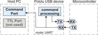 |
The UART serial mode. |
|---|
UART: In this mode, the TX and RX lines can be used to send commands to the Maestro and receive responses from it. Any byte received on RX will be sent to the Command Port, but bytes sent from the Command Port will be ignored. The TTL Port is not used. The baud rate on TX and RX can either be automatically detected by the Maestro when a 0xAA byte is received on RX, or it can be set to a fixed value specified in bits per second (bps). This mode allows you to control the Maestro (and send bytes to a serial program on the computer) using a microcontroller or other TTL serial device.
Other serial settings:
Enable CRC: If checked, the Maestro will require a cyclic redundancy check (CRC) byte at the end of every serial command except the Mini SSC command (see Section 5.d).
Device Number: This is the device number (0–127) that is used to address this device in Pololu Protocol commands. This setting is useful when using the Maestro with other devices in a daisy-chained configuration (see Section 5.g).
Mini SSC offset: This parameter determines which servo numbers the device will respond to in the Mini SSC protocol (see Section 5.e).
Timeout: This parameter specifies the duration before which a Serial timeout error will occur. This error can be used as a safety measure to ensure that your servos and digital outputs go back to their default states whenever the software sending commands to the Maestro stops working. The serial timeout error will occur whenever no valid serial commands (or qualifying native USB commands) are received within the specified timeout period. A timeout period of 0.00 disables the serial timeout error. The resolution of this parameter is 0.01 s and the maximum value available is 655.35 s. The native USB commands that qualify correspond to the following methods in the Usc class: setTarget, setSpeed, setAcceleration, setPwm, disablePWM, and clearErrors. Running the Maestro Control Center will not prevent the serial timeout error from occurring, but setting targets in the Status tab or playing a sequence will.
Never sleep (ignore USB suspend): By default, the Maestro’s processor will go to sleep and stop all of its operations whenever it detects that it is only powered by USB (no VIN supply) and that the USB has entered the Suspend State. However, this behavior can be disabled by checking the Never sleep checkbox.
Related products


Home | Forum | Blog | Support | Ordering Information | Lists | Distributors | BIG Order Form | About | Contact
© 2001–2026 Pololu Corporation
