Support » Pololu USB AVR Programmer User’s Guide »
7. Measuring Voltages Using the SLO-scope
A second bonus feature of the Pololu USB AVR programmer is the severely limited oscilloscope (SLO-scope), which uses lines A and B as inputs to measure TTL-level voltages at a sample rate of up to 20 kHz. The SLO-scope has two operating modes:
- Two 8-bit analog channels sampling at 10 kHz
- One 7-bit analog channel (A) and one digital channel (B) sampling at 20 kHz
The SLO-scope can measure voltages between ground and approximately 5 V (depending on your computer’s USB bus voltage); you can measure higher voltages by passing them through an external voltage divider before connecting them to the programmer. The following schematic shows a general voltage divider circuit that can be used to scale down an input signal to the SLO-scope’s required 0 – 5 V range:
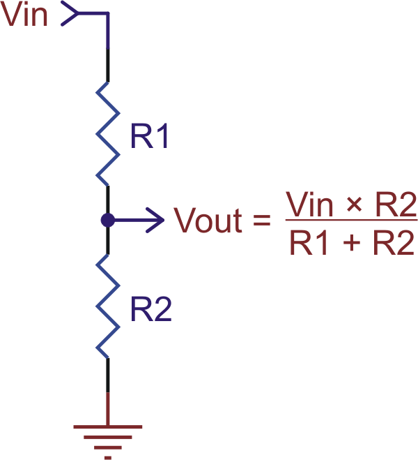 |
The total resistance of R1+R2 should be as large as possible to minimize the divider’s effect on your signal, but it should not exceed 100 kΩ or so.
Runing the Pololu SLO-scope Application
The SLO-scope application for Windows comes with the Windows software and drivers (Section 3.a). At this time, the SLO-scope can only be used under the Windows operating system.
To start the SLO-scope application, open the Start menu and navigate to:
- All Programs > Pololu > SLO-scope
The SLO-scope application was written as a Visual C# 2008 project: SLO-scope client C# source code (56k zip)
Using the Pololu SLO-scope Application
This application connects to the programmer, streams data from the SLO-scope, and provides the basic functionality of a 10 or 20 kHz oscilloscope.
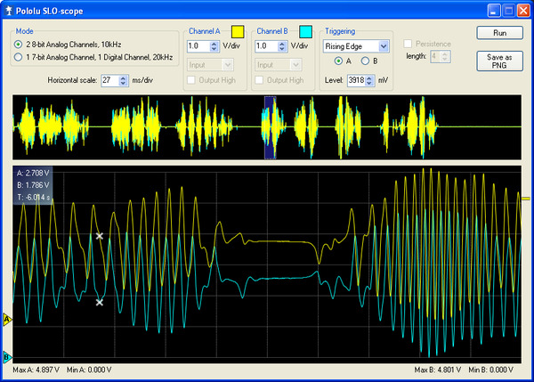 |
Pololu SLO-scope client for Windows. |
|---|
Controls are available for setting the SLO-scope operating mode, adjusting the horizontal and vertical scales, and configuring lines A and B as digital outputs.
To start capturing data, click the Run button in the upper right corner. If the horizontal scale is such that it takes more than 200 ms of data to fill the lower SLO-scope pane, the data will continuously stream across the pane. If the lower pane displays 200 ms of data or less, the pane will draw all of its data at once when it has enough new data to warrant an update (or, if triggering is enabled, when the trigger event is satisfied). In this latter time domain, you can enable the persistence feature (check the Persistence checkbox) to cause the data on the screen to fade out over time when the next update occurs. The Length parameter determines how long it takes for the data to fade. The upper SLO-scope pane shows a summary of all of the data currently stored in memory. This is approximately 10 seconds of data when running at 10 kHz and 5 seconds of data when running at 20 kHz.
To review the captured data in detail, click the Stop button (in the same place that the Run previously occupied). When the SLO-scope is stopped, you can scroll through the data stored in memory by clicking on the portion of the upper pane that you want to inspect or by clicking and dragging the cursor in the lower pane to pan through the data more finely. You can zoom in and out by changing the horizontal scale, and you can inspect the data in the lower pane by hovering over it with your cursor. A purple rectangle highlights the portion of the upper pane is visible in the lower pane.
You can adjust the vertical scaling of a channel’s data by changing its volts-per-division parameter, and you can adjust the amount of data that is shown in the lower pane by changing the SLO-scope’s milliseconds-per-division (horizontal scale) parameter.
Triggering can be used when horizontal scaling is 20 ms/div or less. You can trigger on rising or falling edges of either channel A or channel B, and you can adjust the trigger level by directly setting the value in millivolts or by dragging the trigger level scrollbar on the right side of the lower pane to the desired position. When triggering is enabled, the data in the lower pane will update whenever a trigger event occurs. Triggering can help you to better identify and analyze periodic signals (such as motor noise, PWMs, etc.) while the SLO-scope is running.
To change the color used to draw a channel’s data, double click on the colored square in either the Channel A or Channel B box.
To change the vertical position of the 0V level of a channel, click and drag that channel’s corresponding 0V-indicator triangle on the left side of the lower pane.
While the SLO-scope is running, lines A and B do not function as serial handshaking lines as discussed in Section 6.a. Rather, the SLO-scope can control the I/O states of A and B. The SLO-scope application lets you configure these pins as inputs (their default settings when you first enable the SLO-scope) or as digital outputs driven high or low.


Home | Forum | Blog | Support | Ordering Information | Lists | Distributors | BIG Order Form | About | Contact
© 2001–2026 Pololu Corporation
