Support » Pololu USB AVR Programmer User’s Guide » 6. Communicating via the USB-to-TTL-Serial Adapter »
6.a. Communicating via the Serial Control Lines
Firmware version 1.04 (released on April 29th, 2011) fixes a problem with the RTS and DTR control signal outputs. If you want to use those outputs, you should upgrade your firmware to version 1.04. Please see Section 9 for information about upgrading your firmware.
Firmware version 1.03 (released on December 22nd, 2010) inverts the TTL serial port’s control signals so that 0 V corresponds to 1 and 5 V corresponds to 0, making it consistent with other USB-to-TTL-serial adapters. Prior to version 1.03, the opposite convention was used.
In addition to transmitting bytes on the TX line and receiving bytes on the RX line, the USB-to-TTL-serial adapter can use programmer pins A and B as serial handshaking lines of your choosing. Each pin can be configured as an input or an output by identifying it with a serial handshaking line. The table below shows which handshaking lines are available (CTS is not available because there is no provision for it in the USB CDC ACM subclass).
| Direction | Name | .NET System.IO.Ports.SerialPort member |
|---|---|---|
| Output | DTR | DtrEnable |
| Output | RTS | RtsEnable |
| Input | CD | CDHolding |
| Input | DSR | DsrHolding |
| Input | RI | N/A |
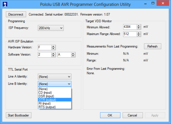
By default, pins A and B are high-impedance inputs that are not identified with any handshaking line. To use pins A and/or B, you must configure them to be serial handshaking lines using the Pololu USB AVR Programmer Configuration Utility (see Section 3.e). The programmer stores the configuration in persistent memory.
 |
Pins A and B can be identified with serial handshaking lines using the Pololu USB AVR Programmer Configuration Utility. |
|---|
After your have associated pins A and/or B with serial handshaking lines, you can take advantage of the I/O capabilities of A and B. For input lines, this means you can get a digital reading of the voltage on the line over USB. For output lines, this means you can set the voltage on the line over USB. A voltage of 0 V corresponds to a logical 1, while a voltage of 1 V corresponds to a logical 0.
For example, if you wanted to connect your Pololu USB AVR Programmer to an AVR running the Arduino bootloader, you could configure pin A to be DTR and then connect pin A to the AVR’s reset line. When the Arduino software sets DTR to 1, the programmer will drive the line A low, which puts the AVR in reset mode.
You can read input lines and/or set output lines by either using a terminal program that supports control signals (such as Br@y Terminal) or by writing a computer program. The Microsoft .NET framework is free to use and it contains a SerialPort class that makes it easy to read and write bytes from a serial port as well as set and read the control signals. Here is some example C# .NET code that uses a serial port in this way:
// Choose the port name and the baud rate.
System.IO.Ports.SerialPort port = new System.IO.Ports.SerialPort("COM4", 115200);

// Connect to the port.
port.Open();

// Assuming that line A is identified with RTS, and your firmware version is 1.04
// or greater, this drives line A low (0 V).
port.RtsEnable = true;

// Assuming that line B is identified with DSR, and your firmware version is 1.03
// or greater, this takes an inverted digital reading of line B.
if (port.DsrHolding)
{
    MessageBox.Show("Line B is low.");
}
else
{
    MessageBox.Show("Line B is high.");
}

// Disconnect from the port so that other programs can use it.
port.Close();
When the SLO-scope feature is enabled, it assumes control of pins A and B and uses them as analog inputs (or digital outputs controlled by the SLO-scope application). Pins A and B temporarily lose their serial handshaking line associations while the SLO-scope is active, but these associations are restored once the SLO-scope is disabled. You can disable the SLO-scope via the SLO-scope application or by unplugging the programmer and plugging it back in.


