Pololu Blog » Engage Your Brain »
Simple LED circuit abstractions
The simple LED circuit from last time is a great first circuit for everyone interested in electronics because it is so forgiving. If you connect something backwards, you probably won’t break anything, and otherwise, it should just work. However, that forgiving nature of the circuit can beguile newcomers into thinking everything is that simple, and though there are many web pages out there discussing the circuit, they usually do not address the abstractions and simplifications that are in play and why we can use them in this instance. So, that’s the topic for this post.
First off, here is the circuit:
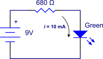 |
How many assumptions does this drawing represent? Here are just some of them:
- The battery is at 9 V.
- The battery voltage does not change with the current we draw from it.
- The battery can safely supply the amount of power we need.
- Our wires have zero resistance.
- The wires can carry the current we want them to carry.
- The resistor has the resistance we think it has.
- The resistor behaves according to Ohm’s law.
- The resistor can dissipate the power we need it to dissipate.
- The LED voltage drop is constant.
- There is no capacitance or inductance.
- The circuit always existed in its completed state.
- Nothing is touching our circuit.
- There are no magnetic fields fluctuating around our circuit.
Fortunately for newcomers who want to build at least something that works, it turns out that these assumptions are quite reasonable, in this case. If you have never actually built this circuit, you should, even if you just hold the parts to the battery by hand:
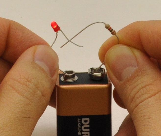 |
If you are paying attention, you might have noticed that I swapped the position of the LED and resistor, that the LED is red instead of green, and that the resistor is a 1 kΩ resistor, not 680 Ω. And that’s part of the reason this is a great beginner circuit: it can be built quite shoddily and out-of-spec, and the basic function of lighting an LED is still preserved. A lot of the reason the circuit is so robust comes down to the very loose requirement of the LED to be “on” and in the small amount of power involved. But, every one of those assumptions I listed have tripped people up once they moved on to more complicated circuits. Let’s now consider why each assumption or abstraction is reasonable in the simple LED circuit and why it might not be justified in other contexts.
Assumption: The battery is at 9 V.
The basic reason for the battery voltage not mattering that much is that it is much higher than the LED forward voltage, which means that most of the battery voltage gets dropped across our resistor. Even if the voltage were twice as high as we expected, the voltage would just cause (approximately) twice as much current to flow through the resistor and thus through the LED. This would be slightly detectable as the LED being brighter, and it might ultimately impact the LED’s life, but we would still say the circuit basically works. Similarly, if the battery voltage were just 5 V, we would now have just 2.9 V to drop on the resistor instead of 6.9 V, so our current would go down to about 3/7 of what we wanted, but the LED would still be on. Since the battery we are assuming to have 9 V can have anywhere from around 3 to 20 volts without it really affecting our circuit, it’s a safe assumption.
Many other circuits, however, do not have such a wide operating range, and they can either simply not do anything or fail spectacularly when the applied voltage is outside of the allowable range. With batteries, you also cannot count on the nominal voltage really being the actual voltage. While you probably won’t see double the nominal voltage on a battery, it’s quite common for a well-charged battery to be 30% above its nominal voltage. And, of course, the voltage on a battery can get arbitrarily low; ideally, your circuits will just transition gracefully into the “do nothing” mode in this situation, but sometimes, you have to take extra precautions (i.e. be really good at “do nothing” mode) to keep from over-discharging the battery and destroying it. Many circuits are also powered by power supplies other than batteries, and each will have some variation from the desired output. Sometimes, as in the case of unregulated “wall-wart” power adapters, the unloaded voltage can be much higher than the voltage on the label.
Abstraction: The battery voltage does not change with the current we draw from it.
Most of the reason we don’t care about the battery voltage changing with current is the same reason we do not care about the voltage in general, though assuming a constant battery voltage independent of current simplified our calculation of the current-limiting resistor. However, you should know that in general, the load you apply to a power supply will affect its voltage, and that the more you vary your current, the more likely it is that your voltage will vary as well. And, if you’re doing almost anything beyond having an LED on forever from an infinite battery, your current will be changing.
I am calling this an abstraction because we know the statement is not true, but we are making the simplification anyway.
Assumption: The battery can safely supply the amount of power we need.
The 10 mA current we used in our calculation just isn’t much current, and just about any normal battery will be able to supply it. However, that does not stay true for long, and once you have a circuit that uses several amps, as will usually be the case once you have motors involved, you will need to pay attention to how much current your battery or other power supply can deliver. If you do not take the right precautions, you can permanently destroy your power supply, possibly in a dramatic and dangerous way.
Abstraction: Our wires have zero resistance.
Assuming our wires have no resistance is a common simplification we make, and it’s usually justified for two reasons: first, the resistance is actually quite low, and second, the resistance is much lower than other resistances in the circuit. Even if you used several feet of wire building the circuit, the resistance would likely be well under one ohm, and this isn’t the kind of circuit where one is likely to use hundreds of feet of wire. And, we are already intentionally putting 680 ohms into our circuit; even if we add several more ohms, we would only be changing the total resistance by less than one percent, which would in turn change our current and LED brightness by less than one percent.
In applications beyond this circuit, though, the resistance of the wire could be significant in three common ways. The first two ways correspond to the reasons it didn’t matter with the LED circuit: you might actually build up a lot of resistance if you’re trying to hook things up that are hundreds or thousands of feet apart, and you might have circuits with very low effective resistances, in which case even your sub-ohm wire resistance becomes significant. The third way your wire resistance can matter is if you have sensitive circuits where things like a few percent of error matter. In our LED case, it didn’t matter; if you are trying to make a precision sensor circuit, you might want to account for or reduce every stray resistance.
Assumption: The wires can carry the current we want them to carry.
 |
Blown trace on a printed circuit board. |
|---|
On this assumption, we are again saved by the 10 mA target current being low relative to what most wires can do. If you have a metal wire that’s not so thin you keep breaking it or losing it, it will handle 10 mA. However, as with the assumption about the battery or power supply being able to deliver the current you need, trouble will arise as soon as you get into higher (but still normal, real-world) currents. Again, a few amps is nothing much when dealing with motors, and that is already enough to literally melt or vaporize thin wires, which you might see most often in the form of traces on a printed circuit board.
Assumption: The resistor has the resistance we think it has.
This assumption mirrors our first assumption about our battery voltage being what we think it is, and for the same reason (resistor being half as big or twice as big will just cause the LED to be half as bright or twice as bright), we don’t particularly worry about things like the tolerance of the resistor we use. However, if we misread the resistor value and used a resistor that was way too small, the LED could burn out, and if we used a resistor that was way too big, we might not see any light from the LED and think we had a bad connection, so it might be worth it to measure the resistor before using it. Obviously, the exact resistance will matter more in some cases than in this one, and getting things wrong will cost more in some cases than in others.
Abstraction: The resistor behaves according to Ohm’s law.
This abstraction works quite well most of the time, and since we don’t even care about the exact resistance in this case, the abstraction works well here. But, there isn’t really such a thing as a perfect resistor, and even something that you buy just for the sake of having it follow Ohm’s law will still be affected by things like temperature (and the very use of the resistor will affect its temperature!). It’s also easy to forget that even things that seem to work like resistors might do so only over a limited range.
Assumption: The resistor can dissipate the power we need it to dissipate.
 |
24 ohm, 1/4 watt resistor does not take 12 volts well. |
|---|
Once again, we are saved by the lower-power aspect of the simple LED circuit. In this case, though, we might not have as much margin for error as we had with assuming the battery or wire could deliver the current. There are multiple expressions for calculating the power dissipated in a resistor (based on substitutions from Ohm’s law), but we know we have a 6.8 V drop at 10 mA, so multiplying those is the easiest way to see that we have about 0.07 W dissipated in our resistor. That’s getting close to the 1/8 W limit of small through-hole resistors, but it’s still quite safe. However, if we were using a higher-power red LED using several dozen mA powered by a 12 V car battery, we could get past the limit of typical 1/8 W and 1/4 W resistors. Once you get past applications like small LEDs, it’s easy to get into trouble if you forget to consider power dissipation, and since parts can literally catch on fire, it can quickly get dangerous.
Abstraction: The LED voltage drop is constant.
We could go through the same “is it what we think it is/can it handle the power” considerations as we did for the battery, wires, and resistor, and I would have basically the same comments since the starting assumption is that the LED will handle around 10 mA at the voltage we used for our calculations. However, it’s worth pointing out that the LED forward voltage is not absolutely constant with respect to current and that it varies from LED to LED, even when they have the same color. In our circuit, it does not matter if the LED has 2.0 V or 2.2 V on it since the difference between the battery voltage and the LED voltage will appear on the resistor, and an extra 0.1 V difference will make just as little difference as it did if the battery changed by that much (the actual power in the LED is slightly different in the two situations, but either way, it’s minimal). But, if you wanted to do something with more LEDs at once, the differences in forward voltage could start to matter, with problems ranging from uneven brightness to the LEDs burning out.
Abstraction: There is no capacitance or inductance.
Capacitance and inductance significantly complicate electronics when we move on to circuits with time-dependent behavior. In this case, though, we are not trying to do anything fancy like turning the LED on and off, so we assume all of the currents and voltages do not change, and once we do not have anything changing over time, any undesired capacitances or inductances would not matter anyway. In most real applications, we do have changing voltages and currents, and in those cases, we have to be aware of both intended and parasitic (undesired but unavoidable) inductors and capacitors.
Abstraction: The circuit always existed in its completed state.
I have mentioned a few times now that nothing is changing (e.g. currents, voltages) in our simple circuit. However, something clearly changed the instant the circuit became complete, and if we do not really want to think about it, we have to assume that the circuit has always existed in its completed state or that there was never a moment when the circuit got turned on. Because we have low voltages, low currents, low inductances, and low capacitances, nothing too remarkable happens when we complete this circuit, but it many cases, turning on can be the most problem-prone phase of operation. You can look at my LC voltage spike article for a discussion of one way you can destroy your circuit before it finishes turning on.
Abstraction: Nothing is touching our circuit.
As you could see in the picture above, the simple LED circuit works fine even when I held the part leads in my fingers. That’s not advisable for most circuits, but most will still be in contact with all kinds of things that can affect the circuits’ operation. In the case of the LED circuit, the current of 10 mA is big (for a change!) compared to the currents that might flow through people or whatever might touch the circuit, so our touching it won’t affect things much. Unexpected items in contact with our circuit also add inductance and capacitance, but as we already covered, that does not concern us in this circuit because we do not have anything changing with time. However, as soon as you get to sensitive circuits, where only microamps are flowing, touching the circuit or building it on the wrong substrate or wrapping it in the wrong material can affect its behavior. A particularly difficult case of this problem is test equipment, which you should remember can affect your circuit just like anything else that touches it.
Abstraction: There are no magnetic fields fluctuating around our circuit.
Electromagnetic waves let us do awesome things, like communicating wirelessly and charging our toothbrushes without exposing ourselves to electrocution. Unfortunately, that also means that these (usually) invisible waves can affect our circuits in complicated and confusing ways. You would have to be in a fairly unusual environment and have long wires coiled up the right way to have any noticeable impact on the LED circuit, and even that would just consist of slight fluctuations in brightness. We are again helped by the LED current being relatively large compared to what we might pick up with our circuit loop, but this type of phenomenon can be a big problem with higher-sensitivity circuits running close to things like motors.
Conclusion.
As I hope you see, there really are a lot of assumptions in play for just this little circuit, and we have to make sure we are aware of them as we move on to more complex circuits. This is also why we often recommend simplifying circuits and reducing loads from motors to just LEDs to try to track down the source of tricky problems. Please let me know if there are any more basic assumptions I didn’t mention or if you have good stories of problems you have encountered because one of these assumptions turned out not to be valid.
-

Simple LED circuit
- 30 November 2010One of the simplest circuits you can build is an LED powered by a battery. Unfortunately, many people who think they know some electronics (and...
-
Parallel circuits
- 17 December 2010If you have a limited or informal electronics education, parallel circuits might be the kind of topic you glossed over or have forgotten about....
0 comments
Post a comment


Home | Forum | Blog | Support | Ordering Information | Lists | Distributors | BIG Order Form | About | Contact
© 2001–2026 Pololu Corporation


