Pololu Blog » Engage Your Brain »
Simple LED circuit
One of the simplest circuits you can build is an LED powered by a battery. Unfortunately, many people who think they know some electronics (and even multiple job interviewees with supposed electrical engineering degrees) cannot actually draw the schematic for the simple circuit or calculate the appropriate component values. Can you? (If you can easily do it, you should probably skip the rest of this post.)
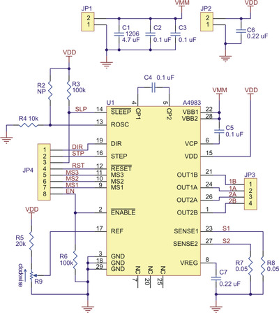
I’ll stick this unrelated schematic here so you don’t just see the answer before you think about it.
 |
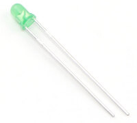
You might be wondering what kind of battery and LED we’re talking about. You can draw the basic circuit without values, but for the one calculation you need to perform, you will need some specific values. Let’s say you have a 9V battery and we’re talking about a typical, green indicator LED. You know, one of these:
 |
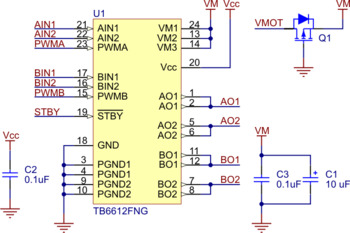
And, in case you have a big monitor, one more decoy:
 |
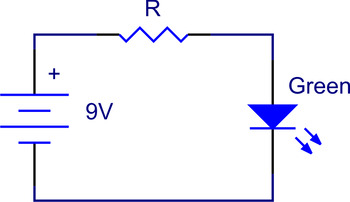
Okay, time to get to our real circuit for today. Ideally, you pictured something like this right away:
 |
There are a few key points to note:
- You have to have a resistor in the circuit. We’ll calculate the value in a bit. The resistor can be on either side of the LED.
- The LED and battery have to be in the correct direction.
- The three components have well-defined schematic symbols you should know. It probably does not matter exactly how many cells you show in your battery, how many zig zags you have in your resistor, and what exactly the arrows on your LED look like, but if you think you know electronics and find yourself drawing boxes for all three of these parts, you might want to go easy on how much electronics you claim to know.
Specifying the appropriate resistance takes a bit more work if you want to have a defensible answer. There are a few basic rules that we have to apply: Kirchhoff’s voltage law, and then Ohm’s law. Kirchhoff’s voltage law tells us that if we go around a closed loop such as this circuit, the voltage differences across each component in the loop must add up to zero. This should seem intuitively obvious since it is basically a restatement of the principle of conservation of energy: if you went around the loop and ended up with a non-zero result, you would have some source of voltage you hadn’t accounted for. If you go around the loop clockwise and starting at the negative side of the battery, you can see that the 9 V of the battery must be countered by 9 V of voltage drop over the resistor and LED:
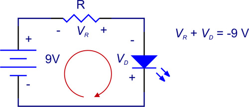 |
If you’re uncomfortable with the idea of -9 V representing the voltage across the resistor and LED, you can flip what you call positive and negative:
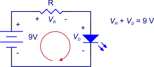 |
You should note that this version is less consistent about the correlation between the direction we are going around the loop and what we are calling positive and negative. I remember this positive and negative business being confusing and seeming inconsistent when I was a kid, and that wasn’t helped by teachers who didn’t really get it either pointing out that current actually flows in the other direction than we say it does. The thing to keep in mind is that if you are consistent, things should work out (and in this case of following the voltages around a loop, we’re not even talking about current). The first drawing is labeled appropriately; just remember that since VR is negative in that case, the left side, which is labeled “-”, will be the positive side if you measure it with a meter. It’s good to be able to figure out the details in case you get stuck with your intuition, but it’s also good for your qualitative understanding to tell you that the 9 V supplied to the circuit by the battery will be dissipated by the resistor and LED, which are not adding energy to the circuit.
Once we’ve established that the LED and resistor have 9 V across them, we are almost ready to use Ohm’s law to decide what resistance we want. Ohm’s law is simple enough that anyone who wants to do anything with electronics should just know it:
Because we have just a single loop in our circuit, the current has to be the same through all three components—otherwise, some current would magically be coming out of or going into nowhere. To specify the current, we just have to know what an appropriate current for our LED is. We’ll use 10 mA since that’s fairly typical and easy to work with. A common mistake I see for those who get this far is that they want to apply Ohm’s law to the combination of the LED and resistor; that is, they want to use 9 V for the V in the equation. This is where the color of the LED comes in: different LED colors have different forward voltage drops. A green LED has around a 2.1 V drop at 10 mA (the chemistry in the LED will also matter, and some designer LEDs with special “true greens” have higher voltages). What makes the LED different from a resistor (i.e. Ohm’s law does not apply) is that even at 5 mA or 20 mA, the voltage drop will be about the same. Also, if you did have a perfect 2.1V battery and connected it to the LED without any resistor, the current could get arbitrarily large and destroy the LED. That’s why we need the resistor in there, to limit the current.
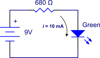
If the LED voltage is basically 2.1 V no matter what and the LED and resistor add up to 9 V, we see (by applying Kirchhoff’s voltage law again) that the resistor will be left with 6.9 V across it. We now have the current through the resistor, 10 mA, and the voltage across it, 6.9 V, so we can plug those numbers in and arrive at a resistance of 690 ohms. However, 690 Ω is not a standard resistor value, so if we really had to build this circuit, we’d use the nearest standard value, 680 Ω. Here’s our final circuit:
 |
If you could do this instantly on your own, great; but, don’t get too excited: in the grand scheme of electronics, this is about as basic as 2+2=4. Next time, I’ll go over how even this simplest of circuits has a lot of simplifications and why we can get away with them. In closing, here’s a checklist of things you should know or brush up on if you don’t know them:
- Know the schematic symbols for basic electronics components.
- Know Ohm’s law.
- Be able to apply it to a resistor.
- Know that it does not apply to most things, including LEDs and batteries.
- Understand (be able to apply) Kirchhoff’s voltage law.
- Know that LEDs have approximately constant voltages across them when they are in their operating range, and that that voltage varies with color.
- Know that an appropriate current for a small LED is around 10 mA.
- Be aware that actual physical components will not necessarily be available in the exact value you would like.
-

Estrella Intersects the Plane
- 29 November 2010This art installation by Matthew Richard uses 10 OctoBrite DEFILIPPI modules, 80 RGB LEDs, 40 servos, 7 servo controllers, and an Arduino.
-

Simple LED circuit abstractions
- 8 December 2010The simple LED circuit from last time is a great first circuit for everyone interested in electronics because it is so forgiving. If you connect...
4 comments

Life is much simpler if you use conventional current, which says current leaves the + battery terminal. (Yes, the electrons go the other way.) You can think of it as the way the positive charges move.

I have an LED of unknown specifications, expect of course for what I can see: Color, size and shape. To make things more difficult the LED has already being used so the leads have been clipped and shortened.
Q #1: How do I find the LED polarity?
Q #2. How do I find the optimal voltage/current this LED should operate at?
Q #3. Can I destroy an LED if I connect the polarity backwards?
Q #4. With any given LED and DC voltage, by connecting a variable resistor in series, that will enable me to "eye-ball" an average LED luminance (e.g. not too dim, not too bright), can I determine a safe resistor value for my circuit?
--
I am NOT an electrical engineer, just the basic DIY type, tinkering with various, simple to average small electronics projects. I often end up buying components of known values, but I also "harvest" used components from abandoned, used, broken equipment I find. I'm sure you see my problem. Resistors and capacitors can be read with a good multi-meter. ICs, etc can usually be "de-coded" by the letters/numbers on them. But with diodes/led etc., I am lost.
Can you help?
Thank you!

In general, the longer lead on an LED is the positive lead; however, since you cannot determine which lead was longer with them already cut, I recommend using the continuity test on a multimeter to determine which lead is the anode.
The LED voltage is usually determined by the color it emits, so you might try searching for an LED color voltage chart to determine its rated voltage. For the current, you will probably have to look it up in its datasheet.
It is possible to destroy an LED by connecting the polarity backwards, but the voltage required to break it is usually significantly higher than the forward voltage of the LED.
Using a variable resistor to determine a safe resistor value might work; however, it is probably easier to just buy new LEDs so you can get all the necessary specifications and calculate the appropriate resistor value.
- Jeremy

Post a comment


Home | Forum | Blog | Support | Ordering Information | Lists | Distributors | BIG Order Form | About | Contact
© 2001–2026 Pololu Corporation


