Pololu Blog »
How to make a Balboa robot balance, part 1: selecting mechanical parts
 |
This is the first post in a series about how to make a Balboa 32U4 robot balance. Today I will talk about selecting mechanical parts for your Balboa. We offer a variety of gearmotors and wheels that work with the Balboa, and the Balboa kit includes five different gear ratios for the external gearbox, so even without considering non-standard modifications, there are many possible configurations of the robot. In this post I will give you some guidance about choosing the right parts.
[See also: Part 2: inertial sensors, Part 3: encoders, Part 4: a balancing algorithm, or Part 5: popping up and driving around.]
First of all, it’s worth keeping in mind that when your robot is balancing, undisturbed, on a flat surface, the motors will barely be moving, so the performance of the parts will not matter much. Any combination of the parts we discuss here will work for basic balancing, so you should probably be selecting your parts based on the most extreme maneuvers you want your robot to be able to do: driving fast, “popping up” from a lying-down position, riding over rough terrain, and so on. You might also be concerned about precision in the motion: encoder resolution, gearbox backlash, and the ability to drive smoothly at low speeds.
Wheels
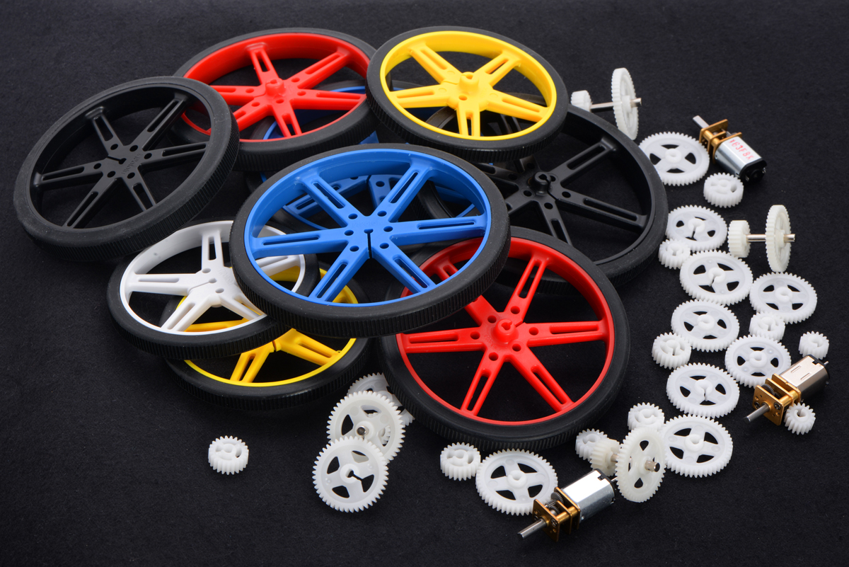
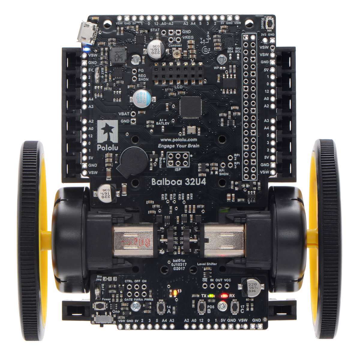
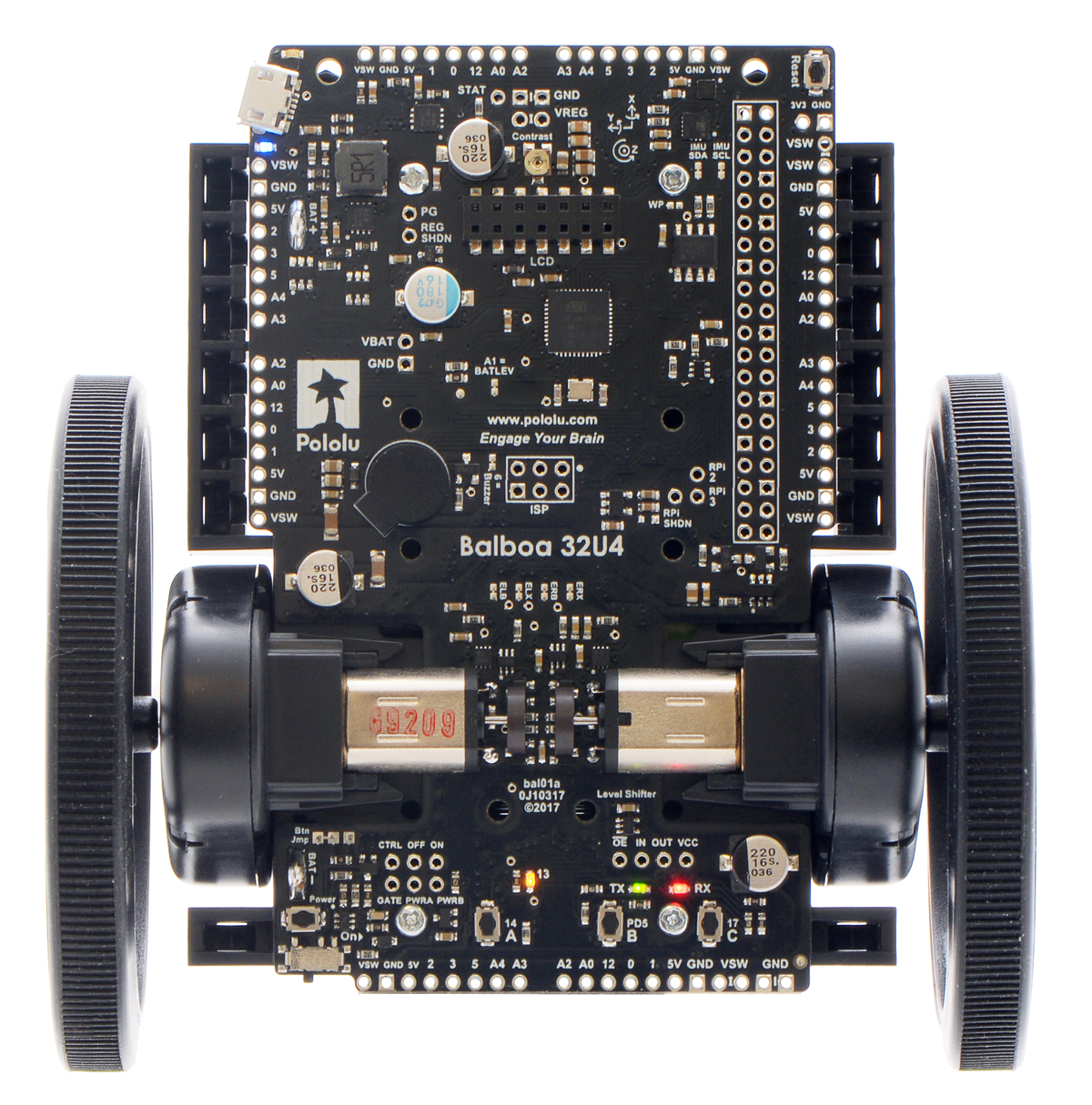
Balboa’s external gearboxes have a 3mm D-shaft output that is compatible with our 70mm, 80mm, and 90mm wheels. In general, a larger wheel will give the robot more stability and allow it to move faster and drive over larger obstacles. One downside is that its torque will be reduced, so it might have trouble with more dynamic maneuvers. I recommend starting with the 80mm wheels if you are unsure or don’t have any special needs; we used these for most of our testing. Be careful if you pick the 70mm wheels; you only get a few millimeters of clearance. Here is a comparison of the three sizes:
|
|
|
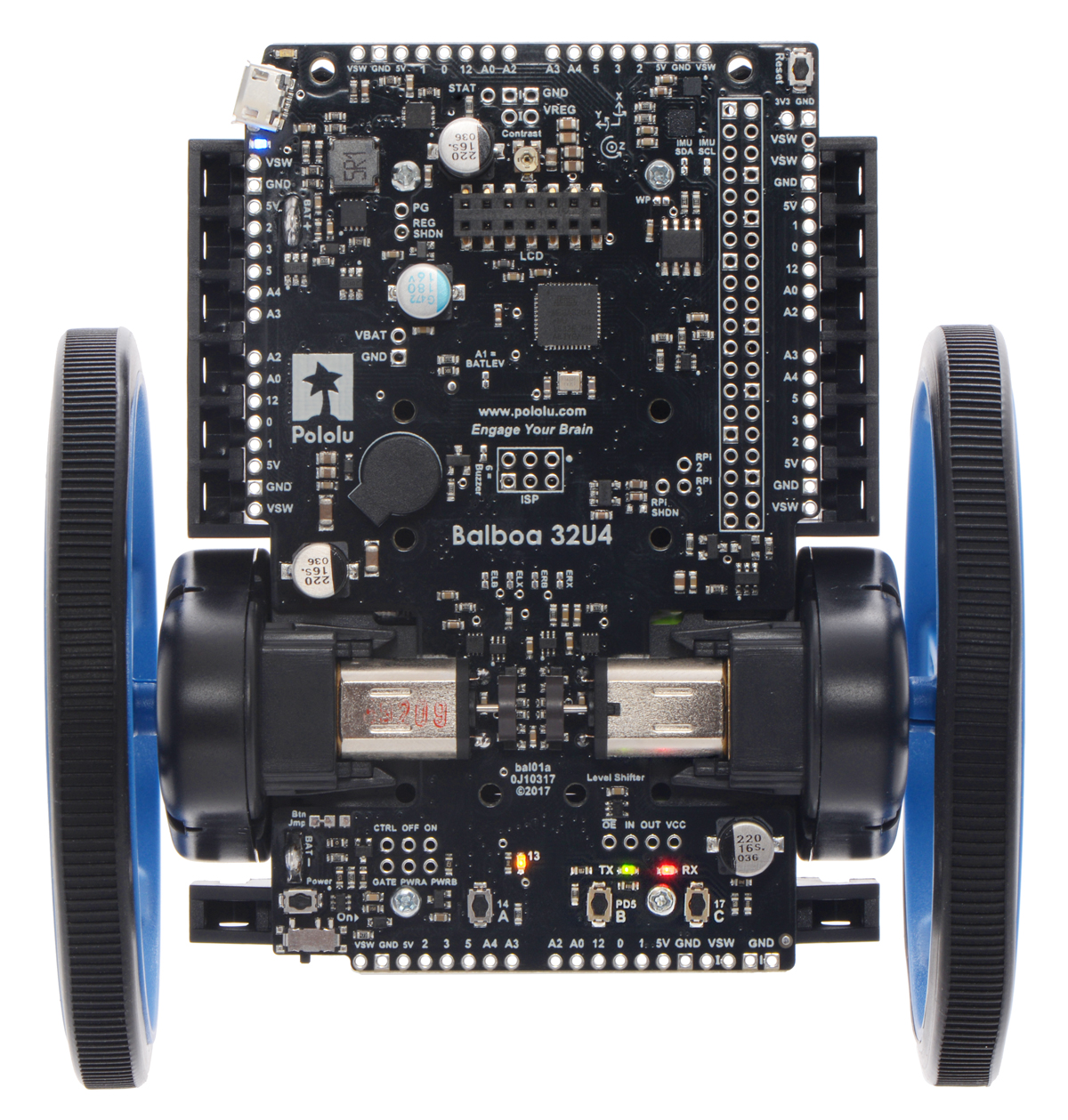
Note that we offer the wheels in five different colors so that you can customize your robot, and if you want to use non-standard wheels, we carry a few 3mm wheel adapters that might work.
Motors
Balboa uses two micro metal gearmotors, which are held by motor brackets built in to the chassis. While almost all of our micro metal gearmotors will fit, encoders are a key feature of the Balboa robot. As far as I know, it is very hard to make a stable balancer without them, so you should almost certainly choose motors with extended motor shafts. We recommend the high-power carbon brush versions for longer life, specifically the 30:1, 50:1, or 75:1 versions (all denoted “HPCB 6V with Extended Motor Shaft”).
Higher gear ratios give you more torque and less speed; if you don’t know what to choose, you should probably get the 50:1 motors, but continue reading for how the external gears affect these performance numbers. Note that it’s quite hard to change the motors after they are soldered into place!
External gearing
The Balboa’s gearmotors drive external gearboxes with plastic gears that increase the gear ratio and also protect the gearmotors from external torques and loads. Our kit includes five different gear ratio options, listed in the Balboa kit gear ratio chart (447k pdf), letting you select a final gear ratio between 1.64 and 2.88 times the gearmotor’s gear ratio:
| Gearmotor | ||||
|---|---|---|---|---|
| 30:1 | 50:1 | 75:1 | ||
| External gearbox |
49:17 | 86.1 | 148.3 | 218.5 |
| 47:19 | 73.9 | 127.3 | 187.5 | |
| 45:21 | 64.0 | 110.2 | 162.5 | |
| 43:23 | 55.8 | 96.2 | 141.7 | |
| 41:25 | 49.0 | 84.4 | 124.3 | |
When writing our demo code we used the 50:1 gearmotors with 45:21 plastic gears. For this video we happened to use 75:1 gearmotors and the 41:25 gears, which have about the same overall gear ratio and therefore about the same performance:
To get an idea of the performance of these different options, let’s look at speed. The 50:1 motor, for example has a rated no-load speed of 625 rpm at 6 V. The Balboa uses six AA batteries, with a nominal voltage of 7.2 V, so we expect a higher top speed of ``7.2/6*625 text( rpm) = 750 text( rpm)``. The external gears reduce this number; with the 45:21 combination, for example, we would get an output speed of approximately ``21//45 * 750 text( rpm) = 350 text( rpm)``. With wheels of diameter ``D``, the corresponding horizontal speed is
``v = {350*pi D}/ {60 text( s)}``
so that for the 70, 80, and 90 mm wheels, we would compute top speeds of 1.3 m/s, 1.5 m/s, and 1.6 m/s. This should give you some idea of the performance, but keep in mind that when actively balancing, you don’t want to get close to those numbers: if the robot is driving at top speed and starts to fall forward, there will be no way for it to recover.
Torque varies inversely with the speed: the more speed you have, the less torque you will have available for acceleration and for maneuvers like “popping up”. I recommend picking a combination that has enough speed for what you want to do, but not too much.
 |
Animated gif of Balboa demonstrating “popping up”. |
|---|
Besides changing the speed and torque by a simple factor of the gear ratio, the plastic gears also have some non-ideal effects on the drive train that depend on how tightly they mesh. Tightly-fitting gears add friction, reducing speed especially at low power settings, while loosely fitting gears have more backlash, which can make it hard to hold a precise position. In my tests I found that our 49:17 and 47:19 gears fit relatively tightly, creating friction that made my Balboa harder to control. Based on this, I recommend using the other three options, at least at first.
It is possible, however, that by using the encoders you could compensate for all of that friction in software, and the reduced backlash of these gears could be an advantage. Look for my next post, where I will start getting into the programming!
Continue reading with Part 2: inertial sensors.
Related products


-

Zumo 32U4s with CMUcam5 Pixy
- 17 March 2017Customer Carlos Ambrozak developed an “Introduction to Robotics” course that includes a lab where students work on visual object tracking. The...
-
New #2 and #4 screw lengths
- 20 March 2017We added five more screws to the hardware category of our catalog:
1 comment

Reference: “In my tests I found that our 49:17 and 47:19 gears fit relatively tightly, creating a lot of friction that made my Balboa harder to control.”
As for tight fitting gear sets, I have used toothpaste on plastic gear sets to speed the “break-in” process. I have used the toothpaste technique on GM10 gearhead-motors with great success.
My technique:
Place a little toothpaste on gear teeth.
Run assembly at speed for a short period: 5 to 20 seconds.
The pitch should increase as the RPM rises: breaking-in.
Check the gear mesh and evaluate.
Clean out the toothpaste and lubricate.
I Love DOW CORNING® MOLYKOTE® 44 High Temperature Silicon Bearing Grease.
Post a comment


Home | Forum | Blog | Support | Ordering Information | Lists | Distributors | BIG Order Form | About | Contact
© 2001–2026 Pololu Corporation
