Pololu Blog »
New product: Logic Level Shifter, 4-Channel, Bidirectional
 |
Level shifting is a common issue when interfacing multiple microcontrollers or other digital logic devices. For example, you cannot directly connect an Arduino running at 5 V to the Wixel, which runs at 3.3 V. Our Wixel Shield for Arduino contains several level-shifting circuits to help you do this.
In some cases, such as connecting a digital sensor output to your microcontroller, a simple voltage divider or transistor inverter might be good enough. However, in many cases a better solution is necessary. I²C, for example, is a common protocol that makes use of a bidirectional communication line. Luckily, a relatively simple circuit consisting of a MOSFET and two pull-up resistors can be used for general-purpose bidirectional level shifting:
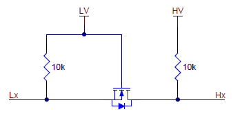 |
Schematic of a single bidirectional logical level shifter. |
|---|
We have used this level shifter circuit on many of our breakout boards operating at a lower voltage, such as the MinIMU-9. It works like this:
- When Lx, the lower-voltage input, is driven low, the MOSFET turns on and the zero passes through to Hx.
- When Hx, the higher-voltage input, is driven low, Lx is also driven low through the MOSFET’s body diode, at which point the MOSFET turns on.
- In all other cases, both Lx and Hx are pulled high to their respective logic supply voltages.
The circuit works for any pair of voltages (within the limitations of the MOSFET) and can be used with most common bidirectional and unidirectional digital interfaces, including I²C, SPI, and asynchronous TTL serial. You can read more about it in NXP’s application note on I²C bus level-shifting techniques (54k pdf).
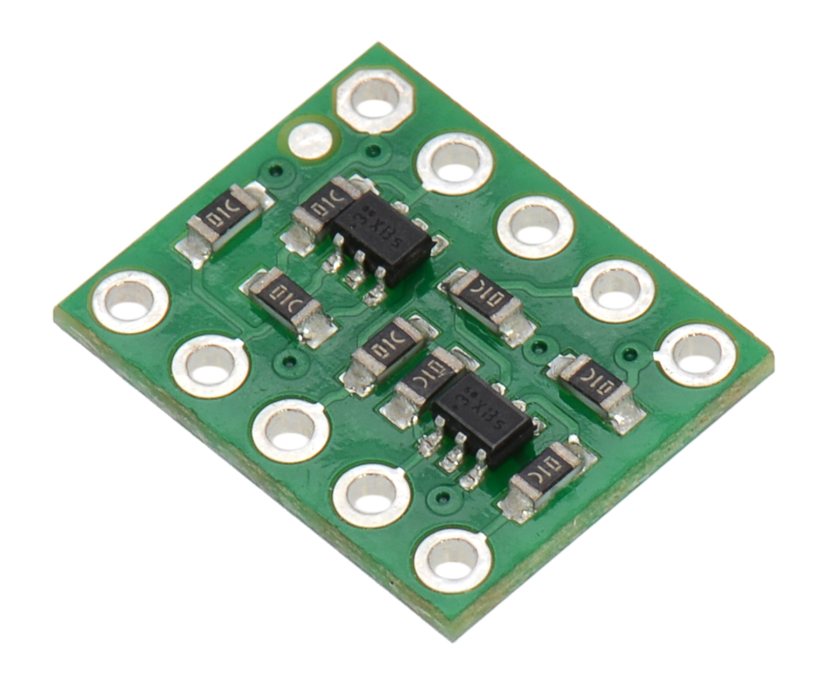
Today we released a logic level shifter board featuring four of these bidirectional channels:
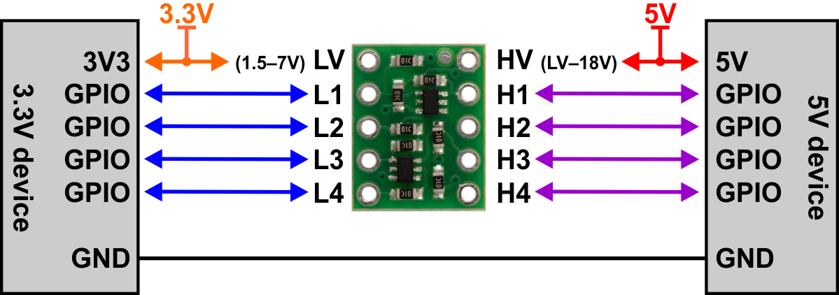 |
Our board can convert signals as low as 1.5 V to as high as 18 V and vice versa, so you can use it for almost any logic-level signals that you might encounter in your project. It is also, as far as we know, the smallest bidirectional logic level conversion board out there:
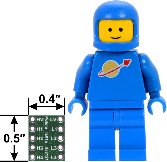 |
Note the use of a more internationally-appropriate size reference than our traditional U.S. quarter. After we put together this image, nobody believed that the board was actually that small, but we verified it several different ways to make sure.
Anyway, with this board’s small size, low cost, and versatility, we think it is something that everyone should have in their toolbox. For more information or to order, see the product page.
Related products

-
Free magazines: May 2014 Circuit Cellar and Elektor
- 1 May 2014Get FREE copies of Circuit Cellar magazine’s May issue and Elektor magazine’s May issue with your order, while supplies last. To get...
-

New distributor: TinySine (Hefei, Anhui, China)
- 6 May 2014We now have a second distributor in China: TinySine, an electronics manufacturer and retailer located in Hefei, Anhui province. They are initially...
14 comments


Is there a specific parameter you are concerned about? We do not want to commit to particular components for boards like these, but the specs should be in line with typical components like this (dual low-voltage MOSFET in a small package).
- Jan


As you noted, this level shifter has a maximum operating voltage of 18V, so it would not be able to shift 24V to 3.3V. We do not have any recommendations for other level shifters that can do higher voltages. If you only want to level shift down from 24V to 3.3V, you might consider using a voltage divider.
- Jeremy


It should be fine over the typical -40 to 125° C range.


Someone posted to our forum about using that level shifter with a 3.3V Teensy to control a NeoPixel ring and it worked for them. Like Jeremy mentions in that same thread, in our tests we were able to use a 3.3V signal directly with our WS2812 addressable LEDs. So, if you are using a 3.3V microcontroller, you might try connecting it directly to your NeoPixel to see if it works without any level shifting. You might also consider adding a 10kΩ pull-up resistor in parallel with the existing pull ups to Lx and Hx on each channel, which should effectively reduce the time constant by half.
-Jon


The 10k pull-up resistors on each of the signal lines on each channel consume current when the channel is in a logic low state. It is possible to calculate a current from your HV and LV supplies using Ohm's law.
-Nathan

When I have a 5V supply connected to LV and a 15V supply connected to HV, I'm getting 5V on all the Lx terminals and 15V on all the Hx terminals even when nothing is connected on the Lx terminals. So the NI 9375 is reading high all the time. Am I doing something wrong?

That is the normal behavior of the level shifter. As described on the product page and in the post above:
- When Lx, the lower-voltage input, is driven low, the MOSFET turns on and the zero passes through to Hx.
- When Hx, the higher-voltage input, is driven low, Lx is also driven low through the MOSFET’s body diode, at which point the MOSFET turns on.
- In all other cases, both Lx and Hx are pulled high to their respective logic supply voltages.
Brandon

I am trying to figure out why they are failing. I am wondering what happens if the H input voltage was greater than HV. For example +18 volts when HV is +13.
Another possibility is voltage spikes on the input lines.
I don't know that these things are actually happening as they did not fail when I was using them, but looking for failure modes.
Any knowledge or suggestions?
Thanks, Russ
It is not clear to me what is causing that problem, and we have not heard of issues like that before, but this is not an appropriate place to get into troubleshooting. You might consider posting a request for help on our forum and include a lot more details about what you are doing (including pictures of your setup that show all of your connections and information about what is providing the 10V signals). Alternatively, you can email us at support@pololu.com.
Brandon
Post a comment


Home | Forum | Blog | Support | Ordering Information | Lists | Distributors | BIG Order Form | About | Contact
© 2001–2026 Pololu Corporation
