Pololu Blog » Engage Your Brain »
Simple hardware approach to controlling a servo
For the last several posts, I have been writing about how hobby servos work and demonstrating the operation of devices made for controlling servos, such as RC receivers and serial servo controllers. That should have given you a good idea of the kinds of control signals we must create if we are to control servos with our own hardware. Today, I am moving on to the subject of controlling servos ourselves, and I will begin with a simple hardware approach.
I should start with the reminder that you can destroy a servo by commanding it past its mechanical limits, so any time you’re making your own servo control devices, be careful. You can limit the likelihood of destruction by operating your servos at a relatively low voltage, so they cannot develop as much torque as they are capable of. I also recommend testing any circuits with a standard servo, which is relatively cheap, more robust than smaller micro servos, yet not powerful enough to easily destroy itself. If you see or hear a servo straining against its end stop, or if it’s getting hot, you should disconnect it or turn off your power immediately.
Before we get to the circuit, let’s go over the basic signal we’re trying to generate: a square wave with a variable positive pulse width of around 1 to 2 milliseconds and a frequency of around 50 Hz.
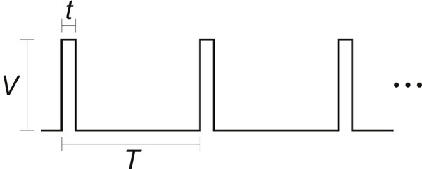 |
Our voltage, V, should be around 3 volts or higher; we need the pulse width, t, to be variable since that is what encodes the desired servo position; and as we saw last time, the period, T, can affect how hard a servo tries to maintain a position but otherwise is not that critical.
The simplest circuit that I know of that can generate this kind of waveform is the two-transistor astable multivibrator:
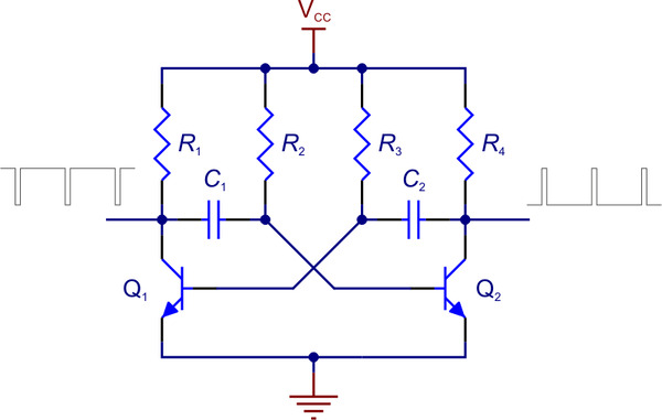 |
Two-transistor astable multivibrator schematic. |
|---|
The multivibrator part refers to a fairly broad range of circuits that alternate between two states; the “astable” part means that neither of the two states is stable, so the circuit keeps oscillating on its own. This circuit has two complementary outputs that are approximately square; because of the symmetry of the circuit, you should see that if the components are all identical, the outputs would each have 50% duty cycles, meaning the outputs would be high half the time and low half the time. (This kind of symmetry-based analysis is generally useful in electronics: if you have equivalent setups, be they the same voltages across resistors of the same value or more complicated circuits like this one, you can quickly estimate solutions or rule out behaviors that would require some asymmetry.) If we begin with this general circuit, all that’s left is to find the right component values to get the frequency and duty cycle we want.
There are lots of web pages out there showing the relevant calculations for this circuit, so I’ll just skip ahead to my answer:
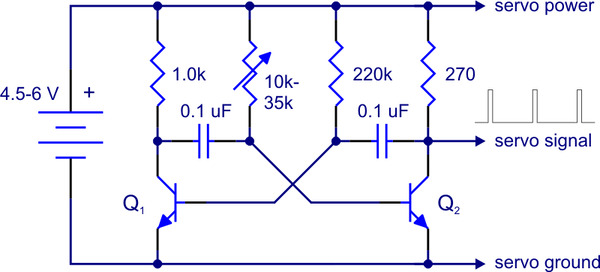 |
Simple hobby servo control circuit. |
|---|
I’ll admit that I went with the guess-and-test/binary search method rather than calculating everything out. I am frequently critical of the “just try connecting things” approach, so I should point out that I did this without a servo connected and with an oscilloscope monitoring the outputs. Also, plugging in different component values that I knew would just cause different pulse lengths and rise times is not equivalent to the recklessness of those who try plugging in power backwards rather than checking how it should be connected.
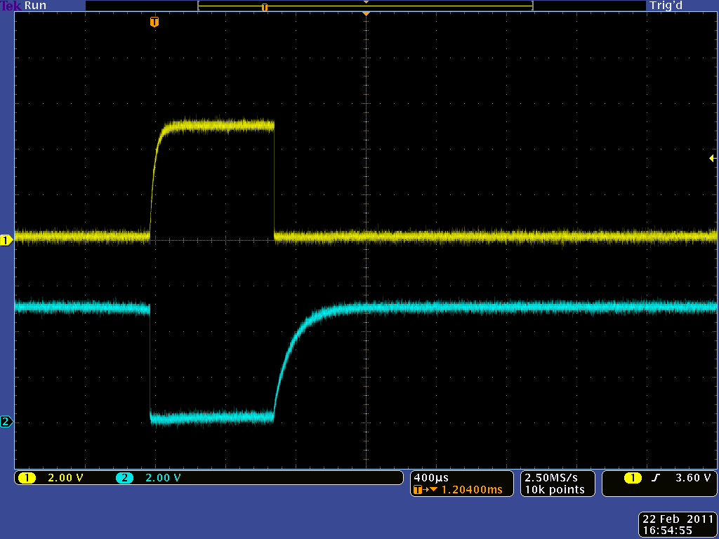
Here is the basic output from the circuit running at 5 V, with the main output in yellow and the complementary signal at the collector of Q1 in blue:
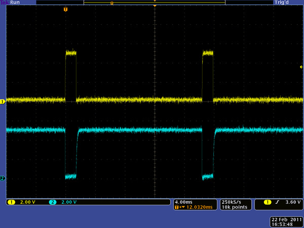 |
Oscilloscope capture of simple servo control circuit output. |
|---|
The resistors R1 and R4 affect the rise time of the signals; we can see that the blue trace has more pronounced curvature as it rises. The signal not being square does not matter for an internal signal like that at the collector of Q1, but since the Q2 collector is our actual control signal, I made the corresponding R4 smaller to enable a faster rise time. The not-quite-squareness of the signal is more apparent as we zoom in in time to see the signal at different R2 settings:
|
|
|


Note that we cannot make R4 too small since transistor Q2 would lose its ability to drive the output low. Also, since the transistor is on (output low) most of the time, using a smaller resistor would cause more power to be wasted in the resistor. R2 combined with capacitor C2 controls the time the pulse is high, so R2 is the resistor we have to vary. In practice, you can get a 10k-35k variable resistor by putting a 10k resistor in series with a 25k potentiometer or using a 50k potentiometer and not using it outside the safe range (the circuit itself will make longer and shorter pulses, but your servo might not like that).
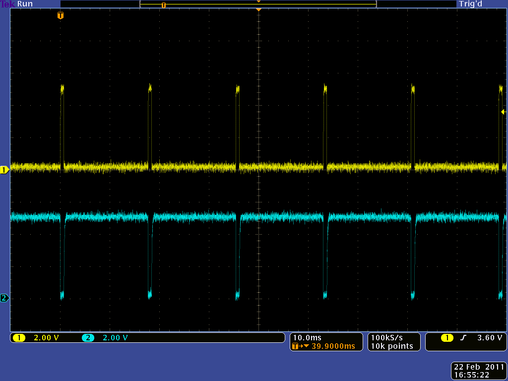
The off-time of the pulse is basically constant and set by capacitor C1 and resistor R3; this means that the pulse frequency varies a bit as a function of the pulse width, but that is an acceptable trade-off for the simplicity of the circuit:
|
|

You might be wondering if it even makes sense to make a hardware servo controller like this. There certainly are a lot of servo control circuits like this available online, and most of them are more complicated in that they use something like a 555 timer chip, which used to be very popular before microcontrollers got really small and cheap. I think the circuit here is minimal but does the basic job of providing rudimentary control of a servo based on a potentiometer input, so if you happened to have the right components sitting around, wiring this up could be quicker than using a microcontroller. If I were serious about wanting a servo controller, I would make one based on a microcontroller since it would give me far more options down the road, so building a servo controller using nothing more integrated than transistors is just a fun exercise.
 |
One thing that made it especially nice for me was that I decided to build my test circuit on a 500-in-1 electronics lab kit, which is the more-advanced version of the 200-in-1 that originally got me started with electronics. I don’t have a 200-in-1 right now, but I suspect the circuit is simple enough to build on just that set, which has no breadboard and instead has all components mounted to spring terminals that can be wired together. I strongly recommend those sets to anyone getting started in electronics, or even those who have played with microcontrollers for a while but do not have much electronics training. As long as I’m plugging stuff, I should also mention that I was quite happy with the Rigol DS1052E, a color, two-channel scope that can save to USB flash drives and which I got for under $400 including shipping (the screen shots in this post are not from that scope).
If you do want to build this circuit for actual use as a servo controller, I should give you a few more warnings. First, the pulse width varies a little bit with supply voltage, which means that if you use this with a battery and set your servo to a position, that position will drift by a few degrees as the battery discharges. Second, although this kind of circuit is frequently shown with higher voltages (e.g. 9 V), the transistor bases get subjected to almost that full voltage, but negative, which is usually more than the base-emitter junction is rated for. This oscilloscope capture has the Q2 base voltage shown in magenta, which might help your understanding of the circuit:
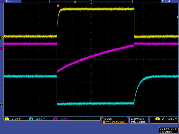 |
Oscilloscope capture of simple servo control circuit with Q2 base voltage shown in magenta. |
|---|
The base voltage drops to about −4 V, turning off the transistor, which causes the output (yellow) to go high. The capacitor connected to the base gradually charges up until the base voltage gets high enough for the transistor to turn on, which brings the output back down.
Conclusion (for now)
At this point, you should have some appreciation of one way of generating servo control pulses. Next time, I’ll move on to microcontroller-based approaches to generating those signals.
-
Only5 - general-purpose, high-performance robot
- 21 February 2011Only5 is designed to be a general-purpose, high-performance robot. It uses many Pololu parts including the Pololu 5" Robot Chassis RRC04A and the...
-

Build Yourself a Bluetooth Controlled Six-Legged Robot
- 4 March 2011This small hexapod using the Micro Maestro is controlled remotely using a Bluetooth module. Very detailed build information is available in this...
8 comments


That kind of topic is well outside the scope of my expertise. "Low voltage" to me is usually below 12 V and maybe even below 5 V, and anything above 30V or so is high voltage to me.
- Jan

Unfortunately nothing comes out from the Multivibrator, my scope doesn't show anything.
I decided I did some mistakes, and I put the circuit together from scratch (using the same components). But same result.
It is long time I'm not using my electronic capabilities and I would have mixed up anything, but it seems to me incredible. Do you think the transistors have burned out or what else ?
Thanks for any help
It could be all kinds of things, and I don't think it's worthwhile to troubleshoot here. I think you should go with something like our micro maestro servo controller:
http://www.pololu.com/catalog/product/1350
It will let you do things like make a script that will use two buttons to do the up/down feature you wanted.
- Jan


Does the (typical?) RC receiver send pulses to multiple servos concurrently or does it cycle through the channels with only one output active at a time? From a current-surge perspective, it seems like the cycling would be preferred.
I don't have enough variety of equipment to answer my own question. :)
--David
I am not sure what is typical. I suspect sequential pulses are more common for cheaper and lower channel-count units, but eventually, the pulses have to overlap if there are enough of them. When we develop products such as the TReX, we make sure that they can read all the channels no matter what their relative timing might be.
- Jan
Post a comment


Home | Forum | Blog | Support | Ordering Information | Lists | Distributors | BIG Order Form | About | Contact
© 2001–2026 Pololu Corporation


